

DT, SRD, and BG Locking Devices
For quarter-turn, multiturn, and bevel-gear operators
Avoid inadvertent handwheel rotation.

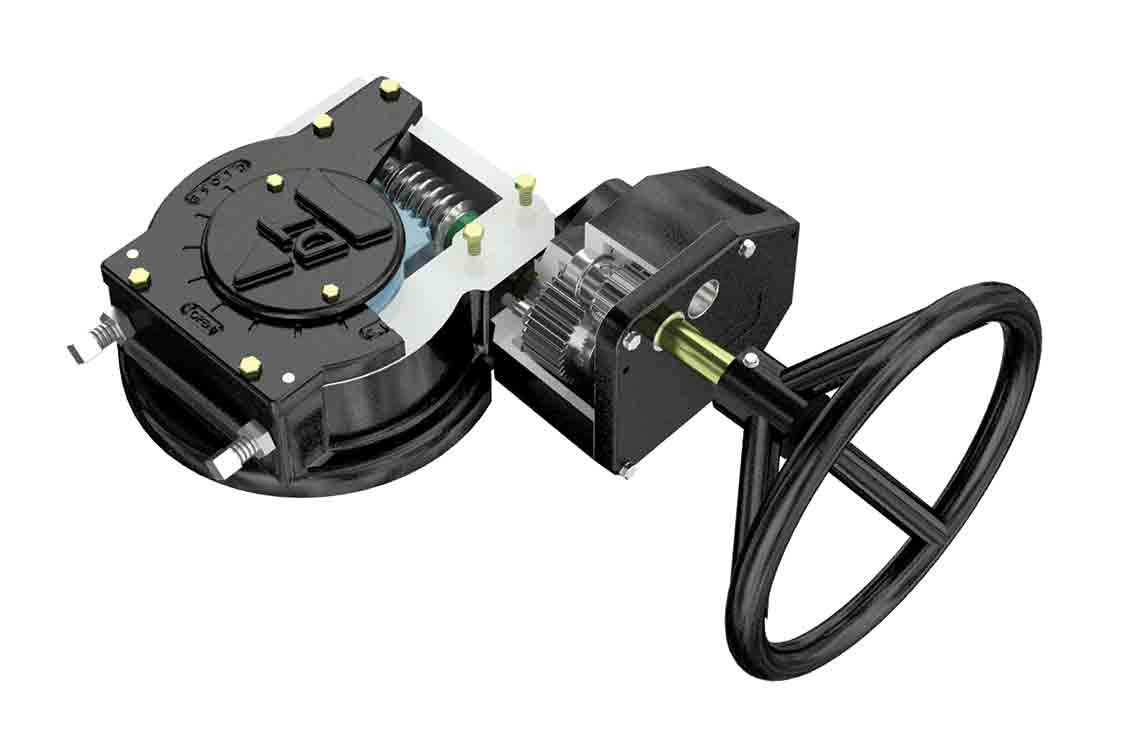
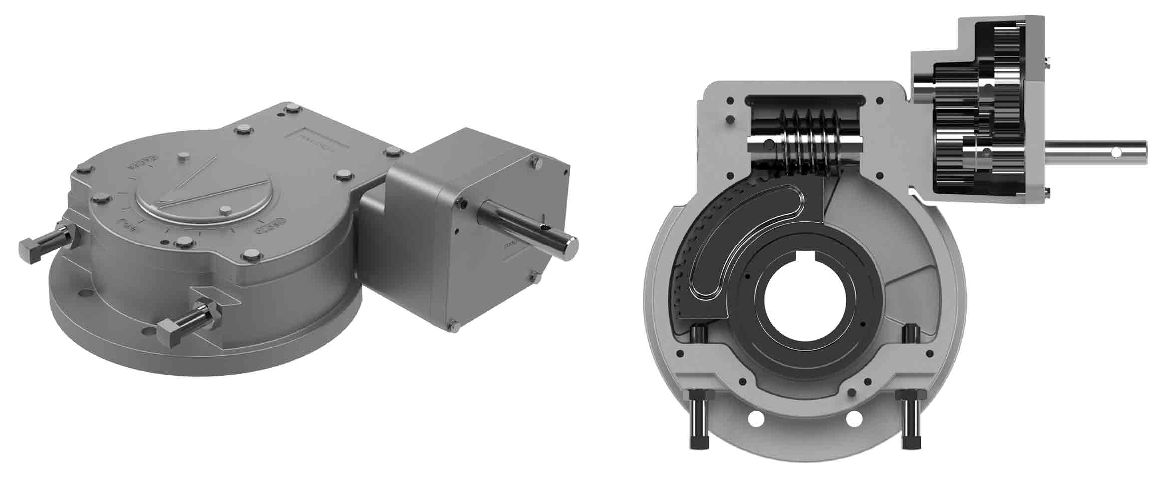
Dynatorque™ 90 quarter-turn worm gears are used to operate quarter-turn valves, dampers, and rotary devices across a wide range of industrial applications. Designed with a self-locking worm gear mechanism, they ensure controlled torque transmission and secure valve positioning, even under demanding operating conditions. Their ability to integrate with both manual and automated systems, together with a broad accessory portfolio, makes them the preferred choice for OEMs; engineering, procurement, and construction (EPC) companies; and end users, worldwide.
Built on a flexible manufacturing platform, the gears are offered with multiple mounting interface dimensions, while custom-machined versions can include bores and bolt holes for direct valve mounting. Gearbox housings are generally made of cast gray iron, with ductile iron and other material options available for specialized applications.
Widely used where quarter-turn valve operation and reliability are critical, including
* American Water Works Association
| Model | Unit Weight, lbm | Max. Output Torque, lbf.in | Gear Ratio | Turns for 90° | Standard Bore, in | Standard Key Size, in | Standard Mounting Pattern (Quantity) and Size, in |
Standard Mounting Pattern (Bolt Circle Diameter), in |
Mechanical Advantage | Handwheel Size, in | Approx. Rim Pull, lbf |
| DT1 | 5.4 | 1,500 | 30:1 | 7.5 | 0.501 | 0.125 | (4) 5/16–18 |
2.756 | 8.1 | 6 | 67 |
| DT3 | 7 | 4,500 | 30:1 | 7.5 | 1.000 | 0.250 | (4) 3/8–16 |
3.250 | 8.10 | 14 | 80 |
| DT7 | 15 | 10,000 | 48:1 | 12 | 1.750 | 0.375 | (4) 1/2–13 |
5.000 | 12.96 | 18 | 86 |
| DT8 | 19 | 8,000 | 30:1 | 7.5 | 1.750 | 0.375 | (4) 1/2–13 |
5.000 | 8.10 | 24 | 82 |
| DT12 | 26 | 16,000 | 57:1 | 14.25 | 2.000 | 0.375 | (4) 1/2–13 |
4.921 | 13.68 | 30 | 78 |
| DT21 | 34 | 26,000 | 60:1 | 15 | 2.500 | 0.500 | (4) 5/8–11 |
5.512 | 22.50 | 30 | 77 |
| DT36 | 78 | 36,000 | 53:1 | 13.25 | 3.250 | 0.750 | (4) 3/4–10 |
6.496 | 19.00 | 36 | 105 |
| DT40 | 78 | 40,000 | 79:1 | 19.75 | 3.250 | 0.750 | (4) 3/4–10 |
6.496 | 27.60 | 36 | 80 |
| DT50* | 105 | 50,000 | 212:1 | 53 | 3.250 | 0.750 | (4) 3/4–10 |
6.496 | 60.80 | 20 | 82 |
| DT54* | 108 | 63,000 | 318:1 | 79.5 | 3.250 | 0.750 | (4) 3/4–10 |
6.496 | 91.20 | 18 | 77 |
| DT60 | 111 | 60,000 | 60:1 | 15 | 3.250 | 0.750 | (4) 3/4–10 |
10.250 | 15.60 | 36 | 213 |
| DT90* | 145 | 90,000 | 240:1 | 60 | 3.250 | 0.750 | (4) 3/4–10 |
10.250 | 49.92 | 36 | 100 |
| DT140* | 148 | 140,000 | 360:1 | 90 | 3.250 | 0.750 | (8) 3/4–10 |
10.250 | 78.00 | 36 | 104 |
| DT200* | 278 | 200,000 | 450:1 | 112.5 | 4.750 | 1.25 × 1.0 | (8) 1 1/8–7 |
14.016 | 120 | 36 | 93 |
| DT220* | 402 | 220,000 | 600:1 | 150 | 6.250 | 1.5 × 1.0 | (8) 1 1/8–7 |
14.016 | 150 | 36 | 81 |
| DT300* | 460 | 300,000 | 1,200:1 | 300 | 6.250 | 1.5 × 1.0 | (8) 1 1/8–7 |
14.016 | 264 | 30 | 75 |
* Units with spur assist
Notes

