The Defining Series: Rod Pump Systems

The Defining Series: Rod Pump Systems
Rod pumps are the most common form of artificial lift for oil wells. Today, these systems are used to lift formation fluids from more than 600,000 wells.
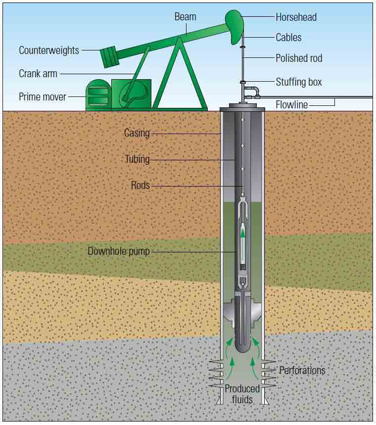
A rod pump system consists of a prime mover, a surface pump, a sucker rod string and a downhole pump (Figure 1). The overwhelming majority of surface units are beam pumps.
Figure 1. Beam pump system. All beam pump systems include a prime mover to rotate a crank arm, whose movement is converted to reciprocal movement through a beam. The beam includes counterweights or a compressed air cylinder (not shown) to help reduce the load on the system during the upstroke. The beam is attached to a polished rod by cables hung from a horsehead at the end of the beam. The polished rod passes through a stuffing box and is attached to the rod string. The rod string is lifted and lowered within the production tubing of a cased well by the reciprocal movement of the beam, enabling the downhole pump to capture and lift formation fluids up the tubing and through a pumping tee that directs the fluid into a flowline.
Surface Equipment
The prime mover may be an internal combustion engine or an electric motor that provides power to the pumping unit. Prime movers deliver high- speed, low-torque power to a gear reducer, which converts that energy into the low-speed, high-torque energy required by the surface pump. A beam pumping unit, or beam pump, converts the rotational motion of the prime mover into a reciprocating vertical motion that lifts and lowers a rod string connected to a subsurface pump.
Engineers design rod pump installations—prime mover type; pumping unit size, stroke length and speed setting; rod and tubing diameter; and downhole pump diameter—based on reservoir fluid composition, wellbore fluid depth and reservoir productivity. Typically, operators make most of these determinations using software programs and then choose an optimal pump speed to attain production targets without overloading the system or overwhelming the formation's ability to deliver fluids to the wellbore.
Beam pumps are constructed in a variety of sizes and configurations. All units work on the same principles but employ design differences to better manage torque, rod wear and footprint. Common alternatives include locating counterweights on the crank arm or on the beam and the use of compressed air rather than weight to assist in load balancing. In addition, changes to crank, gear reducer and motor position relative to the beam, as well as alternative beam designs, can all change system loading.
Surface-Downhole Connection
Sucker rods connect the surface pump to the downhole pump. American Petroleum Institute (API) Specification 11B lists three grades of sucker rods: Grades C, D and K. Grade C and Grade K rods have minimum and maximum tensile strengths of 620 and 790 MPa [90,000 and 115,000 psi], respectively; Grade K is more corrosion resistant than Grade C. Grade D rods have minimum and maximum tensile strengths of 790 and 970 MPa [115,000 and 140,000 psi], respectively and include three types: plain-carbon, alloy and special-alloy steels.
The same API specification on rods allows rod lengths of 25 and 30 ft [7.6 and 9.1 m] and smaller rods, called pony rods, with lengths ranging from 20 to 140 in. [51 to 356 cm]. Operators use pony rods to ensure that the pump is landed at the specified depth.
Fiber-reinforced plastic, or fiberglass, sucker rods may be used to lower overall rod string weight. Fiberglass rods do not corrode and, because they are lighter than steel rods, may be used when loads would otherwise be too great for available surface equipment. Fiberglass rods are highly elastic and will stretch during the upstroke, a fact that designers may capitalize on to generate a downhole pump stroke length that is longer than the stroke length at the surface. However, because fiberglass has little compressive strength, it is rarely used in wells that may subject rods to significant or frequent compressive forces.
Rod strings are selected based on pump and tubing size, pump setting depth, production rate, gas/liquid ratio and the presence of sand, paraffin, salt, scale and foam. Sucker rod strings may be of a single diameter or may be tapered by using two or three rod sizes, typically of the same grade. Operators usually place the smaller-size rods at the bottom of the tapered rod string; the smaller sizes are able to handle the load there and reduce the overall string weight and load on the top sections.
Although continuous rod strings that are coupled only at the surface and at the downhole pump do exist, their use is limited. For the vast majority of rod-pumped wells, these strings are made up of a series of rods threaded at both ends and joined by couplings. Because the outer diameter of the coupling is larger than that of the rod body, couplings routinely contact the tubing wall, particularly in deviated sections. Therefore, in addition to coupling strength and corrosion resistance, system designers take into consideration coupling hardness relative to the tubing to prevent tubing wear.
As an added precaution, designers may place heavier rods, or sinker bars, in the lower section of the rod string to keep the rod string in tension, which reduces buckling and may help prevent contact with the tubing wall. Rod strings may also include stabilizer bars between sinker bars to centralize the rods, further reducing tubing wear.
Rod guides, typically made of reinforced plastics, may be molded onto steel rods at depths where engineers predict the rods will experience side loading due to a deviated wellbore path. The guides act like bearings between the tubing wall and the rod to prevent rod and tubing wear. Sliding guides are able to move between molded guides during the pump cycle, aid-ing production by scraping paraffin from the tubing wall, which helps pre-vent well plugging.
A rod rotator or tubing rotator may be used to rotate the rod a small fraction of a revolution on each stroke of the pumping unit to further extend rod string life. In addition, slow rotation of rod guides may help scrape paraffin from the tubing wall.
Sucker rods are connected to the surface pumping unit by a polished rod. The polished rod, made of standard alloy steel and hard-surface spray metal coating, supports the loads created during the pump cycle and ensures a seal through the stuffing box at the top of the well. The stuffing box is attached to the wellhead or pumping tee and forms a low-pressure tight seal against the polished rod. The seal forms a barrier between the well and the atmosphere and allows flow to be diverted into the flowline via the pumping tee.
Downhole Pump
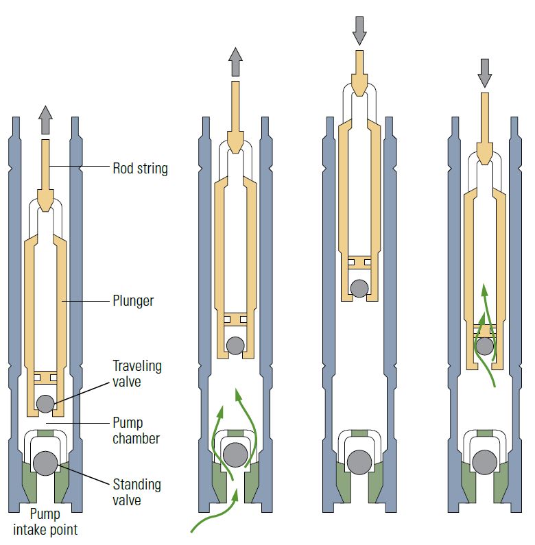
The downhole pump is made up of a pump chamber, a plunger with a traveling valve and a standing valve; it is the mechanism by which fluid is moved up the tubing (Figure 2).
A frequent challenge to downhole pump operation is the entry of gas into the pump, leading to fluid pound or gas interference. Fluid pound occurs when the plunger travels down quickly through low-pressure gas and then suddenly hits fluid; the resulting compressive shock can damage rod strings and the prime mover gearbox. Gas interference is less damaging and occurs when the plunger travels down through high-pressure gas. Both conditions significantly reduce system efficiency.
To combat gas interference, gas separators are placed below the pump to redirect the gas into the wellbore annulus around the pump. Other modifications may be made to the completion to counter or reduce the effects of heavy oil and sand or other produced solids.
Operators can diagnose gas interference, fluid pound severity and many other operating conditions using a dynamometer, which plots rod tension versus displacement measurements at the surface and downhole at the pump. The shape of an ideal downhole graph, called a dynamometer card, is rectangular and indicative of a full pump. Deviations from the ideal shape indicate performance issues, such as gas interference, system leaks, stuck pumps, parted rods and many other anomalies that can be identified and corrected automatically or through manual intervention.
Optimization
Two types of systems are available for improving pump efficiency and protecting the pumping system: pumpoff controllers and variable speed drives (VSDs). When the dynamometer values indicate gas interference, pumpoff controllers can be programmed to turn off the surface unit for a set period, calculated to allow enough time for fluid to migrate through the reservoir and into the wellbore. This method is less complex and less costly than using VSDs but it is effective only in areas where operators have sufficient production history to obtain accurate estimates of how long to shut down the unit.
Based on dynamometer measurements, a VSD reduces the pump speed instead of turning the pump off. This allows time for the pumps to become clear of gas or for liquid levels in the wellbore to rise without having to shut down. Use of VSDs is particularly effective in very-low-permeability formations and shales, where the time required for oil to migrate into the induced fractures and into the wellbore can be difficult to predict even across a single field.
Common for a Reason
Because they are relatively inexpensive to install and operate and have a relatively long life, rod pumping systems are the most common form of artificial lift in use today. They are simple machines that have a long and well-documented history in the industry and they can be easily adjusted to meet changing well or field conditions.
The use of rod pumps is likely to increase as the industry continues to expand its involvement in shale formations and other unconventional plays, which require operators to use high numbers of relatively low-flow-rate wells to exploit each field. Initial high pressures and high production volumes from these hydraulically fractured horizontal wells are quickly followed by low bottomhole pressures and steep production decline rates; production is possible only through the use of artificial lift systems, of which rod pumps are the most efficient at these low rates.
Typically, if not the initial artificial lift system of choice, rod pump systems are installed on many wells as production rates decline and the economics of initial systems are undone by higher operating costs. As a consequence, rod pump systems are likely to maintain their position as the most fre-quently deployed artificial lift method in the world.
Oilfield Review 2016.
Copyright © 2016 Schlumberger.
For help in preparation of this article, thanks to Cosan Ayan, Clamart, France; and Chip Corbett, Houston, Texas, USA.