The Defining Series: Artificial Lift
Published: 09/01/2015

The Defining Series: Artificial Lift
Published: 09/01/2015
Because they lack sufficient reservoir pressure to produce fluids to the surface, the majority of the world’s oil and gas wells are unable to produce at economic rates without assistance. This condition may be the result of pressure depletion over time or be caused by low original reservoir pressure.
To compensate for the lack of natural energy in these formations, operators equip the wells with artificial lift (AL) systems. Artificial lift well candidates are those completed in formations that have economically viable reserves and sufficient permeability for the fluids to move to the wellbore but do not have sufficient reservoir drive to lift those fluids to the surface. Secondary recovery efforts, such as waterfloods designed to capture remaining reserves in pressure-depleted reservoirs, often result in increased fluid volumes that can be lifted to the surface only through AL methods.
When choosing a specific AL system, engineers must consider—in addition to surface conditions based on location—a host of parameters, including reservoir characteristics, production properties, fluid types and operational considerations. Choice of an optimal AL system may be influenced by subsurface conditions, expected production rates, fluid composition, well geometry, reservoir depths, completion configuration and surface facilities. In addition, operators must consider the potential return on their investment by balancing the value of increased production against the cost of hardware for and installation and maintenance of an AL system.
Artificial lift systems are deployed predominantly to extend well life. But these systems may also help shorten the time from first production to well abandonment. For example, operators may gain an economic advantage by accelerating recovery rates, a process that more quickly drains the reservoir, thus saving expenses in situations characterized by high operating costs.
After an operator has established that an AL system is advisable, production engineers choose the type best suited to the situation. For example, electric submersible pumps and gas lift systems are often chosen to boost production in offshore wells because such systems have small footprints, are able to handle high production volumes and may be deployed at significant depths below the wellhead. On the other hand, sucker beam pumps, which require a significant amount of surface space but are reliable, easily serviced and one of the least expensive of the AL options, are often the optimal solution for land-based, marginally economic wells.
Artificial lift systems fall into two basic types: pumping and gas lift. Pumping systems include electric submersible pumps, beam pumps, progressing cavity pumps, plunger lifts and hydraulic pumps.
Electric Submersible Pumps
Perhaps the most versatile AL systems are electric submersible pumps (ESPs). These pumps comprise a series of centrifugal pump stages contained within a protective housing. A submersible electric motor, which drives the pump, is deployed at the bottom of the production tubing and is connected to surface controls and electric power by an armored cable strapped to the outside of the tubing.
An ESP derives its versatility from a wide range of power output drives and from variable speed drives that allow operators to increase or decrease volumes being lifted in response to changing well conditions. Additionally, modern ESPs are able to lift fluids with high gas/oil ratios (GORs), can be designed using materials and configurations able to withstand corrosive fluids and abrasives and can operate in extreme temperatures.
Beam Pumps
A beam pump system is composed of a prime mover, a beam pump, a sucker rod string and two valves (Figure 1). The gas- or electric-driven prime mover turns a crank arm, which causes a beam to reciprocate. The resulting up and down movement lifts and lowers a rod string attached to one end of the beam. The motion of the rod string opens and closes traveling and standing ball valves to capture fluid or allow fluid to flow into the wellbore. In some configurations, the valves are part of an integrated assembly called an insert pump, which can be retrieved using the rods while leaving the production tubing in place. Beam pump equipment and parameters (valves, prime mover, rod and tubing diameter, and stroke length) are determined according to reservoir fluid composition, depth to the fluid top and reservoir productivity. The systems are typically equipped with timers that turn the pumps off to allow fluid time to flow through the formation and into the wellbore. The timer then restarts the pump for a period calculated to produce the fluid that has accumulated in the well.
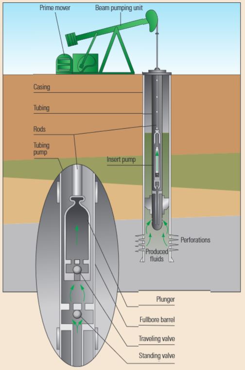
Beam pump equipment and parameters—valves, prime mover, rod and tubing diameter, and stroke length—are determined according to reservoir fluid composition, depth to the fluid top and reservoir productivity. The systems are typically equipped with timers that turn the pumps off to allow fluid time to flow through the formation and into the wellbore. The timer then restarts the pump for a period calculated to produce the fluid that has accumulated in the well.
Progressing Cavity Pumps
The progressing cavity pump consists of a rotor placed inside a stator. The rotor is a screw that has deep round threads and extremely long pitch—the distance between thread tops. The stator has a longer pitch and one more thread than the rotor. When the rotor turns inside the stator, the thread and pitch differences create a cavity within the pump barrel that is filled by formation fluid. The rotor is turned by a rod string connected to a motor at the surface or by an electric-drive motor located downhole at the pump moving the fluid uphole.
Plungers
Plunger lift systems, the simplest form of artificial lift, consist of a piston, or plunger, that has only small clearance through the production tubing and is allowed to fall to the bottom of the well. They are used primarily in high GOR wells to lift liquids out of the well to allow the gas to be recovered. A valve on the surface is closed, which causes natural pressure from the reservoir to build in the casing annulus. At a preset pressure level, the valve on the surface opens and pressure from the annulus enters the tubing below the plunger, which forces it upward. The plunger pushes the fluid column above it to the surface. When it reaches the surface, the plunger enters the lubricator, a short section of pipe, which extends above the wellhead. Because the plunger is no longer in the flow path, the gas that provided the lifting energy can pass beneath it and along the flowline. When the pressure at the wellhead has dropped to a predetermined level, the surface valve closes, the plunger falls from the lubricator to the bottom of the well, and the cycle is repeated.
Hydraulic Pumps
In some situations, operators may install a hydraulic pumping system that pumps a fluid, called a power fluid, from the surface through tubing to a subsurface pump. The subsurface pumps, which may be jets, reciprocating pistons or rotating turbines, force the formation fluids and the power fluid up a second tubing string to the surface. Hydraulic pumping systems offer two specific advantages. Because the subsurface pump is free floating, it can be circulated out of the hole for repair with little intervention cost. And the power fluid, which is typically refined oil, mixes with the produced fluid; the resulting fluid column exerts a lighter hydrostatic pressure than does the formation fluid alone, reduces the resistance to flow and lessens the work required of the downhole pump. As a consequence, hydraulic pumps are frequently chosen for use in heavy oil operations.
Gas Lift Systems
As an alternative or in addition to pump solutions, gas lift systems aid flow to the surface by reducing the density of formation fluids in the wellbore. Gas lift systems consist of valves installed at various depths along the tubing string, which open in response to pressure exerted on them by the rising fluid column. When the valve opens, injected gas mixes with and lightens the fluid column, reducing the hydrostatic and thus the bottomhole pressure. The lower hydrostatic pressure reduces the drawdown pressure and allows formation fluid to enter the wellbore. The less dense fluid column may then be lifted to the surface by reservoir pressure alone.
Optimally, gas lift systems use continuous gas injection at a rate that ensures a steady flow of fluids to the surface. However, if drawdown pressures are insufficient, intermittent injection schemes using gas lift valves may be implemented to allow formation fluids time to enter the wellbore; the gas then lifts slugs of fluid to the surface. Although effective, slug production can cause fluid handling problems at the surface and surges down-hole that may initiate sand production.
Gas valve locations and injection rates are based on the needs of the individual well. Gas lift valves may be set in side pocket mandrels-receptacles that are included as part of the completion design. Because valves are placed in the mandrels using running and setting tools carried downhole via slick-line, when well conditions change, operators can retrieve and change the gas lift valves without pulling the tubing from the well. Technicians can adjust the valves to open at pressures that meet the needs created by the new conditions and replace the valves in the well with minimal intervention costs.
Indispensable Technology
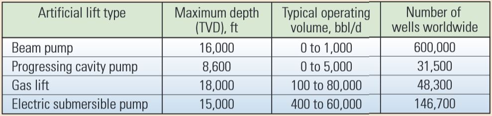
The great majority of the world's approximately one million active oil wells use some form of artificial lift (Figure 2). Such demand has resulted not just in innovation in AL technologies but in an AL discipline. Operators are able to design the best AL system for each well and field and to adjust those systems to meet changing well and reservoir conditions.
Today, AL systems include technologically advanced downhole pumps that can be monitored and controlled remotely in real time and are able to pump thousands of barrels of fluid per day even in wells that have significant amounts of solids. The efficiency of modern beam pumps is such that hundreds of thousands of stripper wells in the US are able to remain profit-able while producing less than 2.4 m3 [15 bbl] of oil or 2.5 m3 [990 Mcf] of gas per day. Since most oil wells and fields eventually rely on AL to continue production, these advances ensure that operators are able to provide a continuous stream of oil and gas to an energy-hungry world.
Oilfield Review 27, no. 2 (September 2015).
Copyright © 2015 Schlumberger.
For help in preparation of the article, thanks to Kyle Hodenfield, Houston, Texas, USA.