The Defining Series: Blowout Preventers
Published: 01/01/2016

The Defining Series: Blowout Preventers
Published: 01/01/2016
Before the development of blowout preventers, operators allowed pressured fluids to flow uncontrolled from formations to the surface and into the atmosphere. Only after the pressure supporting these blowouts abated and surface pressures fell to a manageable level were rig workers able to cap the well. Blowouts were dangerous for the crew, threatened the well-being of the surrounding environment, damaged drilling equipment, wasted resources and caused irreparable harm to the producing zone.
In 1922, Harry Cameron and Jim Abercrombie designed and manufactured the first blowout preventers (BOPs). Assemblies of valves and other devices installed atop a wellhead during drilling operations are called BOP stacks; they provide a means by which rig crews are able to contain unexpected flow and high pressures. They allow crews to manage these influxes by injecting dense fluids down the well, which stop, or kill, the flow of formation fluids; this kill operation is accomplished while preventing well fluids from being released into the atmosphere.
Within the E&P industry, the terms blowout preventer, BOP stack and blowout preventer system are used interchangeably. During drilling and completion operations, they are the second barrier to formation flow; hydrostatic pressure at the formation created by a column of drilling fluid and zonal isolation provided by casing and cement constitute the primary barrier.
The individual BOPs that constitute a system are stacked vertically atop the well. They are aligned to allow access through them into the wellbore while their various functions provide a variety of methods for sealing the well during drilling, completion or intervention operations. They are sized to fit the internal diameter of the wellhead and expected surface pressures.
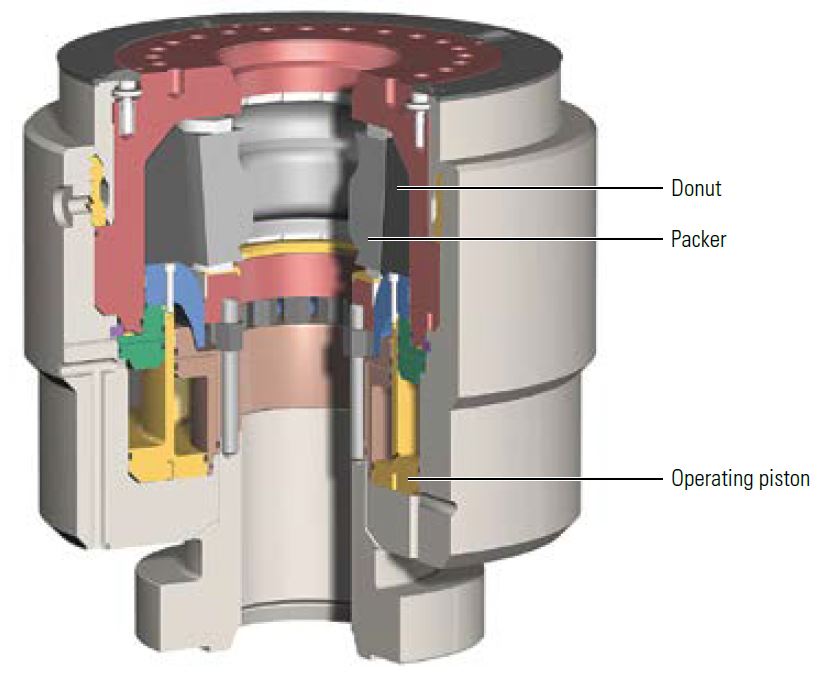
Blowout preventer stacks typically include annular BOPs and ram-type BOPs. Annular BOPs were introduced to the industry in 1946 by Granville Sloan Knox. These devices force circular steel-reinforced rubber elements to close on and create a seal around drillpipe or other tools that may be in the wellbore at the time of shut-in (Figure 1). When annular BOPs are shut in around a pipe, the pipe may be moved up or down or rotated without breaking the seal. Designed to prevent flow up the casing-drillpipe annulus, annular BOPs are also able to seal a clear wellbore in which no obstruction is present although doing so reduces the rated working pressure of the sealing element by 50%.
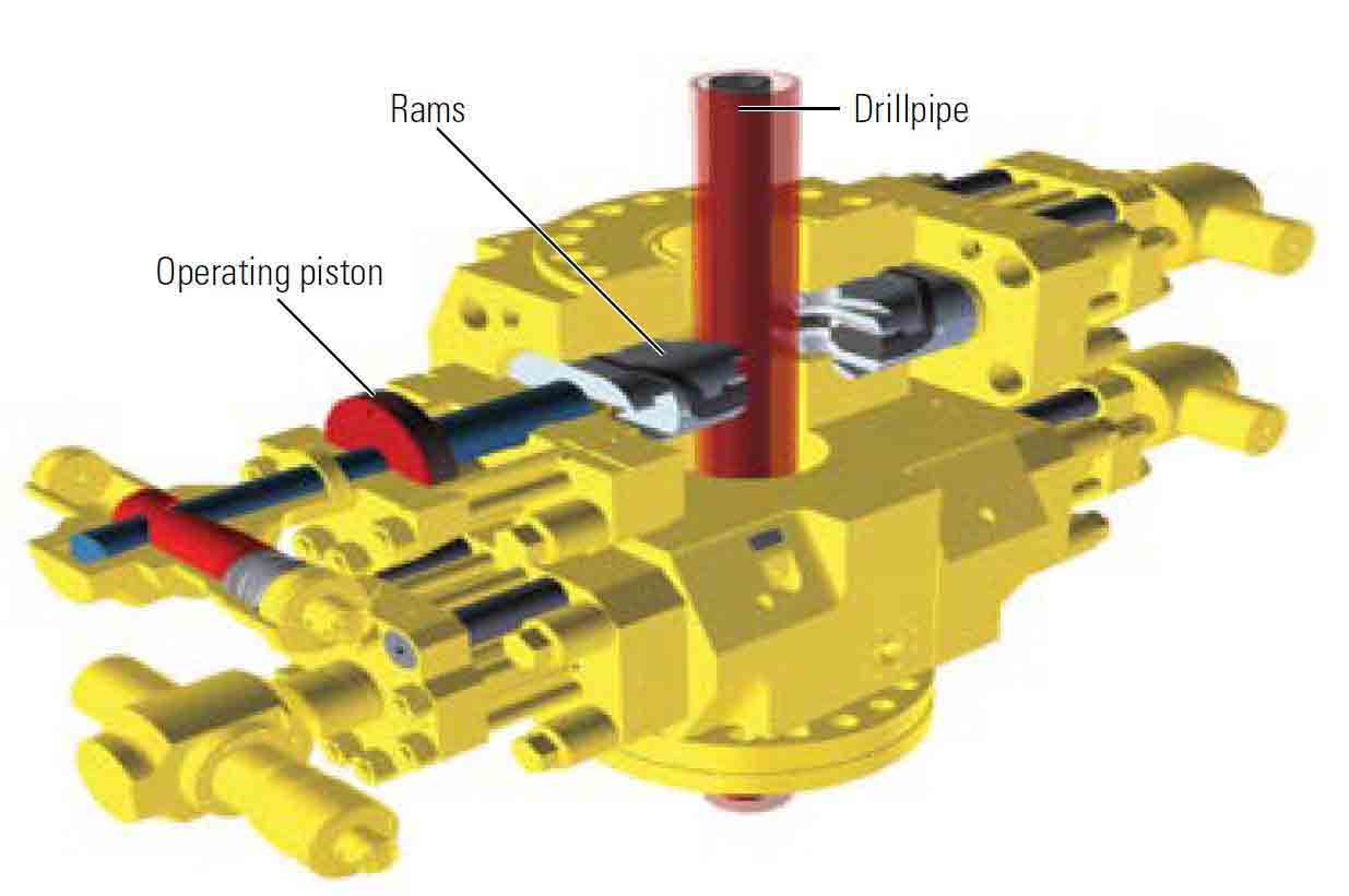
Ram-type BOPs include rubber-faced steel rams that are brought together to create a seal or, like annular BOPs, form a seal around a tool in the wellhead (Figure 2). Shear rams are high-strength hydraulically powered rams that are able to sever drillpipe. They include casing shear rams and blind shear rams. Both are designed to cut drillpipe or other obstructions in the well. Blind shear rams can completely seal the well. Casing shear rams, while not able to form a seal, typically are able to cut larger size tubulars than those that blind shear rams can cut.
Drillers use a control system to actuate rams that is comprised of accumulator bottles containing pressurized hydraulic fluid, a hydraulic fluid storage reservoir, a pumping system and hydraulic piping. The hydraulic fluid is directed to a desired function on the BOP stack via a remote control panel.
Sealing against high pressure and cutting through drillpipe require significant force. Blowout preventer rams are forced closed and reopened using hydraulic power that is stored and ready for use at all times during drilling and completion operations in an accumulator system. An accumulator consists of cylinders containing hydraulic fluid under high pressure. The hydraulic fluid is directed to the BOP rams to drive them to close or open against well pressure.
Drilling rigs are equipped with a choke manifold, operated remotely, that is used to control flow from the well. Typically, flow from the well passes through a fixed choke. To clean up or test a well using the drilling rig and BOPs before the well has been completed, the operator may use the manifold to redirect flow through an adjustable choke, which provides a means to accurately control flow rate and backpressure levels. The ability to adjust choke size allows the operator to maintain a specified flow rate for some length of time and to change the rate to meet test requirements. The test engineer may also reduce the choke size to impose backpressure on the formation, which reduces flow velocity and may prevent production of formation sand or water or gas breakthrough.
The majority of well control incidents involve unexpected formation fluids and pressure influxes, or kicks. These influxes occur when the drill bit enters a zone that has a higher than expected pore pressure. When a kick is detected, the driller typically stops drilling, lifts the bit off-bottom and closes an annular or ram preventer. The kick is then circulated out of the well through a flowline from the wellhead beneath the sealing element of the BOP stack. The rig crew then pumps a fluid down the well. The density of this fluid is greater than that of the drilling fluid in the hole at the time of the kick, and its density is calculated to create a hydrostatic pressure at the formation that will contain the influx.
The flowline below the BOP is a high-pressure chokeline. The chokeline carries the drilling fluid and influx from the wellhead to the choke manifold. A second high-pressure flowline opposite the chokeline is connected to the mud pumps. If the normal method of circulating down the drillstring is not available, this kill line provides an alternative path for the driller to pump fluids downhole and control, or kill, the well.
Because BOPs deployed on jackup drilling rigs remain on the surface, they are similar to those used in land operations. In deeper water, where use of a jackup rig is not possible, floating drilling units use subsea BOPs that are installed atop the subsea wellhead after the surface hole has been drilled, cased and cemented. Both the subsea BOP and the subsea wellhead are located on the ocean floor. Subsea BOPs are equipped with more complex control systems and typi-cally are of larger bore diameters and higher working pressure ratings than are their surface counterparts.
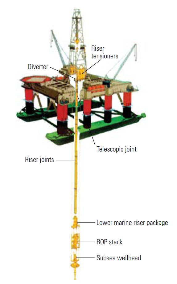
Subsea BOPs consist of two sections—a lower marine riser package (LMRP) and the lower stack (Figure 3). The riser connects the rig to the LMRP, typically made up of an annular BOP, a control system and remotely activated valves designed to release gas from the riser. The LMRP connects to the lower BOP stack, which contains a minimum of four ram type preventers and the choke and kill lines.
To allow some lateral rig movement, subsea BOP systems include flex joints. They also have hydraulically operated connectors that connect the LMRP to the lower BOP stack and the BOP stack to the wellhead. In the event of an emergency, the crew can disconnect the rig from the BOP at the LMRP and secure the well by closing the shear rams of the lower BOP stack by simultaneously using a single command.
For safety and environmental reasons, an order to close the BOP rams must be executed quickly. In water depths of less than about 1,220 m [4,000 ft], BOP systems can use a system in which the hydraulic power is directly transmitted to the required function through an umbilical. However, because this direct hydraulic system cannot achieve the required execution time in deep water, drilling rigs typically employ an electrohydraulic multiplex (MUX) system. Because MUX systems initiate subsea functions via electrical signals, they minimize the time between control system activation and full closure of the rams to secure the well.
Standard influx control procedures depend on the BOPs to seal the well when the driller detects an influx. The driller then allows the shut-in well pressure to stabilize before using one of several methods to circulate out the kick and regain control of the well. Although these methods have been viable for decades and remain so today, ultradeepwater drilling environments and higher pressures have caused some operators to consider dynamic well control methods.
Dynamic well control is available to operators that are drilling wells using rigs that have managed pressure drilling (MPD) equipment and a crew trained in the method. During MPD operations, the bottomhole pres-sure (BHP) is kept constant by increasing or decreasing backpressure on the formation. When the well does experience an influx, the driller can increase backpressure to shut off formation flow without closing in the well. This allows gauges in the drillstring to continue to report downhole pressures to the surface in real time and to minimize the volume of the influx. The driller is able to then circulate the kick out of the well while maintaining a constant BHP and without interrupting drilling operations.
Dynamic well control may allow drillers to more efficiently deal with some influxes and avoid ceasing drilling operations for every kick detected. However, these methods are intended only as an adjunct to standard practices and BOP systems, not as a replacement. In the event of significant or high-pressure influxes, the rig crew must follow standard well control practices as outlined by industry associations and regulatory agencies and based on BOP systems operation. As such, the venerable BOP, while continually evolving to meet the requirements of extreme water depths and pressures, will long remain an indispensable part of all drilling and completion operations.
For help in preparation of this article, thanks to Laura Gardner and Matthew Givens, Houston, Texas, USA.
Oilfield Review 2016.
Copyright © 2016 Schlumberger