The Defining Series: Introduction to Coiled Tubing
Published: 06/01/2014

The Defining Series: Introduction to Coiled Tubing
Published: 06/01/2014
Drilling or workover rigs, iconic symbols of the oil field, are not always required for drilling, completions or maintenance operations. Increasingly, the coiled tubing unit is used for many well intervention operations and certain drilling applications. Coiled tubing (CT) refers to a continuous length of small-diameter steel pipe and related surface equipment as well as associated drilling, completion and workover, or remediation, techniques. Coiled tubing oilfield technology was initially developed for working on live, producing wells. More recently, this technology has gained wider acceptance among operators for an expanding range of workover and drilling applications and for its ability to reduce overall costs. The trend toward extended-reach wells favors CT for its capability to drill or to convey tools and equipment in high-angle wellbores.
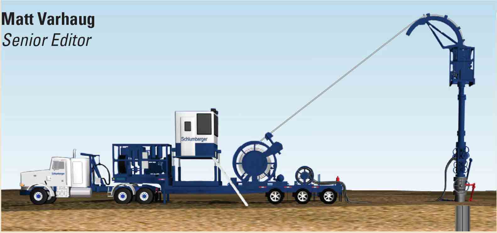
At the center of any CT surface operation is a coiled tubing unit (CTU), the most prominent feature being a reel from which a continuous length of flexible steel pipe is spooled. To deploy tubing downhole, the CT operator spools the tubing off the reel and leads it through a gooseneck, which directs the CT downward to an injector head, where it is straightened just before it enters the borehole. At the end of the operation, the flexible tubing is pulled out of the well and spooled back onto the reel. On the hub of the storage reel, a high-pressure swivel joint enables pumping of fluids through the tubing while the reel rotates to spool pipe on or off the reel.
From the CTU control cabin, the CT operator controls the hydraulically driven injector head to regulate the movement and depth of the CT string. A stripper assembly beneath the injector head provides a dynamic seal around the tubing string, which is essential for running the CT in and out of live wells. A blowout preventer assembly between the stripper and wellhead supplies secondary and contingency pressure-control functions. The entire process is monitored and coordinated from the CTU control cabin.
Coiled tubing is available in diameters of 0.75 to 4.5 in - 2 in. is the most common size. It may range in length from 2,000 to more than 30,000 ft [600 to 9,000 m]. The tubing is coiled in a single continuous length, thus precluding any need for making or breaking connections between joints. This permits continuous circulation while running in or out of the hole.
A Wide Range of Applications
Coiled tubing technology is frequently used to deploy tools and materials through production tubing or casing while remedial work is performed on producing wells. Coiled tubing fulfills three key requirements for downhole operations on live wells by providing a dynamic seal between the formation pressure and the surface, a continuous conduit for fluid conveyance and a method for running this conduit in and out of a pressurized well.
Coiled tubing strength and rigidity, combined with its capability to circulate treatment fluids, offer distinct advantages over wireline techniques in workover operations. In addition to drilling and completion operations, oil and gas companies are using CT to help fish for lost equipment and for conveying well logging tools. It has been used to push or pull equipment through highly deviated or horizontal wellbores and past restrictions or to push obstructions beyond a zone of interest. Well logging is typically per-formed with tools that store data in memory; however, some logging operations use an optional cable to provide surface power and readouts when running tools downhole on CT. Operators also employ coiled tubing to convey and place bridge plugs and mechanical, hydraulic or inflatable packers to establish zonal isolation.
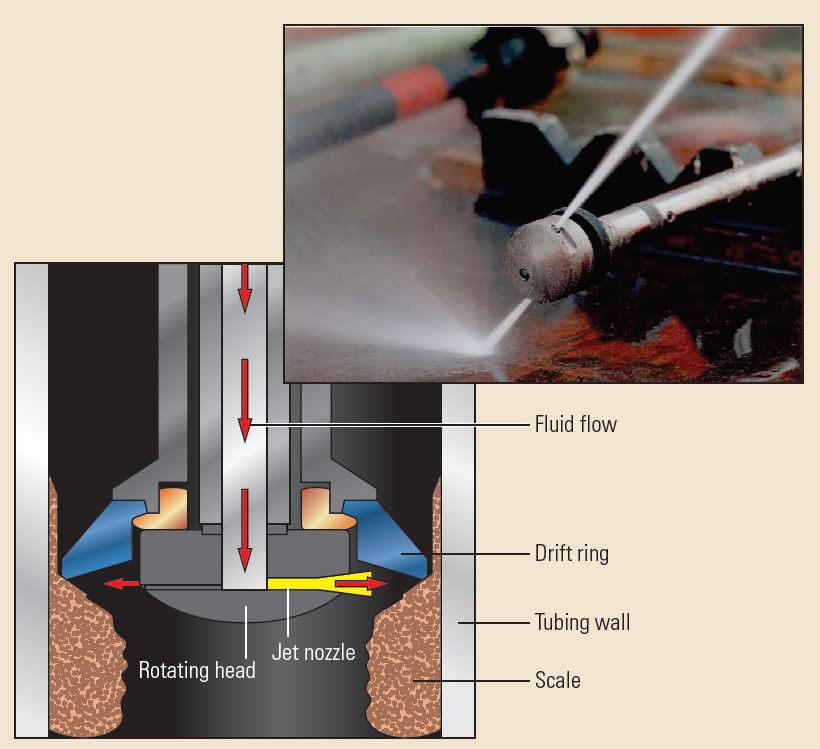
One of the most common applications for CT is the cleanout and removal of fill materials that restrict flow through tubing or casing (at right). Fill material can impede production by blocking the flow of oil or gas. It also may prevent the opening or closing of downhole control devices such as sleeves and valves. Common sources of fill are sand or fine material produced from the reservoir, proppant materials used during hydraulic fracturing operations, debris from workovers and organic scale. Fill removal typically involves circulating a cleanout fluid, such as water or brine, through a jet nozzle run on the end of the CT. The circulating fluids carry the debris back to the surface through the annulus between the CT string and the completion tubing.
Coiled tubing technology also extends to well perforating operations - shooting holes in casing to initiate production in a well. In many wells, perforating guns are run downhole on wireline; however, because wireline tools depend on gravity to reach the target zone, they may not reach target depth in horizontal or highly deviated wells. One alternative is to convey the guns downhole at the end of the CT, which allows for substantially longer gun strings and higher-angle deployments than are possible on wireline. These operations can even be performed with tubing in place.
Its capacity to circulate or inject fluids makes CT especially suited to initiating production in a well. When drilling or workover fluids exert hydrostatic pressures that exceed formation pressure, reservoir fluids are prevented from entering the wellbore. Pumping nitrogen gas through the CT string and into the fluid column is a common method for reducing hydro-static pressure within the wellbore to initiate production. The CT string is run to its target depth, and the nitrogen is pumped through the string to reduce the density of the hydrostatic column. When the hydrostatic pressure of the fluid column drops below reservoir pressure, the well can flow.
Operators frequently utilize coiled tubing as a conduit for accurate placement of cement downhole. Cement is used for sealing perforations or casing leaks, for primary or secondary zonal isolation and for plugs used in kickoff or abandonment operations. A cement squeeze enables the operator to plug casing leaks or existing perforations by pumping cement slurry under pressure into these openings. The cement fills openings between the formation and the casing, forming a seal. Setting a cement plug involves circulating a cement slurry into position using CT then withdrawing the CT string to a point above the top of cement. A slight squeeze pressure is applied if necessary, any cement remaining in the tubing is displaced by a tail slurry then the CT is pulled out of the hole.
Well treatment programs may use CT to convey stimulation fluids that boost production by restoring or improving reservoir permeability. In a matrix treatment, fluids are pumped into a reservoir at a pressure that is greater than reservoir pressure but less than the formation fracture threshold. This technique pushes the fluids through the formation pore spaces without initiating fractures. A similar operation, fracture acidizing, pumps fluids at a pressure that intentionally initiates fractures.
CT can facilitate the installation of production tubing and associated completion equipment. In certain wells, a string or section of CT may be left in the borehole as a permanent part of the completion. CT completions often provide a low-cost approach for prolonging the life of old wells. Typical installations include velocity strings, tubing patches and through-tubing gravel packs.
For example, in some wells, operators choose to install CT permanently as a velocity string inside existing production tubing. In this application, the CT reduces the cross-sectional flow area of the production tubing, thus yielding higher flow velocity for a given production rate and allowing fluids to be carried out of the well more efficiently.
Coiled tubing can serve both as a conveyance and a medium for patching production tubulars. A CT tubing patch can be positioned in a completion to cover mechanical damage or erosion in tubing, to permanently shut off a sliding sleeve or to isolate perforations. Packers set at the top and bottom of the patch hold it in position and provide the seal between the existing completion and CT string.
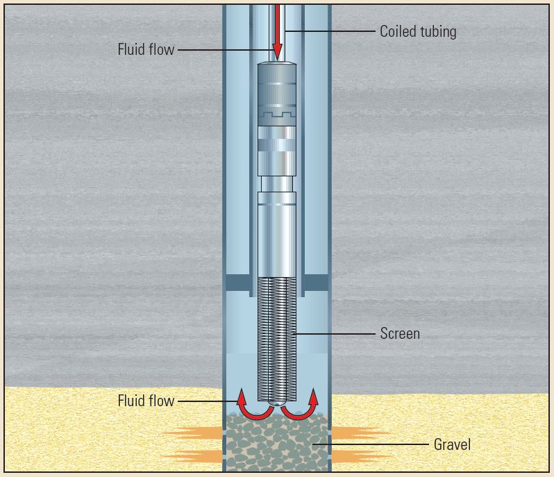
Coiled tubing is also used in completion programs to convey downhole hardware, fluids and materials. Frequently, wells drilled in unconsolidated sands require the wire mesh screen of a gravel pack (GP) to prevent sand production. Common GP installations involve a washdown procedure. First, the CT string is run to the GP depth. Gravel is then pumped through the coiled tubing. The CT string is retrieved to the surface, and a GP screen assembly is attached. As the cylindrical screen is run to the top of the gravel, fluid is pumped through the CT to agitate the gravel and settle the screen into place across from the perforations (at bottom right). The CT string is then retrieved to the surface. The GP keeps the sand in place while allowing formation fluids to flow through it. Should sanding begin later in the life of a well that does not have a GP, coiled tubing offers a means of installing a through-tubing GP completion, in which GP screens are installed through the existing production tubing without removing the original completion hardware.
CT technology has expanded into openhole operations, to include drilling and associated activities. Coiled tubing drilling (CTD) can accommodate a variety of applications, including directional or nondirectional wells. CTD is carried out with a downhole motor and, compared with conventional drilling applications, uses higher bit speeds and lower weight on bit. In directional wells, a steering assembly is required to direct the well trajectory. CTD is used in both overbalance and underbalance drilling applications.
Significant Advantages
CT equipment and techniques present several advantages over those used in conventional drilling and workover operations. These advantages include rapid mobilization and rig-up, fewer personnel, smaller environmental foot-print and reductions in time associated with pipe handling while running in and out of the hole. Such capabilities are especially important in deep or high-angle wellbores. Coiled tubing can help the operator avoid the risk of formation damage inherent in killing a well by allowing continuous circulation during well intervention operations. These advantages may yield significant cost savings over conventional drilling or workover techniques.
Oilfield Review Summer 2014: 26, no. 2.
Copyright © 2014 Schlumberger.
For help in preparation of this article, thanks to Rich Christie, Sugar Land, Texas, USA.