The Defining Series: Directional Drilling Practices
Published: 10/01/2014

The Defining Series: Directional Drilling Practices
Published: 10/01/2014

The practice of directional drilling traces its roots to the 1920s, when basic wellbore surveying methods were introduced. These methods alerted drillers to the fact that supposedly vertical wells were actually deflecting in unwanted directions. To combat this deviation, drillers devised techniques to keep the well path as vertical as possible. The same techniques were later employed to deliberately deflect the well path to intersect hard-to-access reserves.
The first intentionally drilled directional wells provided remedial solutions to drilling problems: straightening crooked wellbores, sidetracking around stuck pipe and drilling relief wells to kill blowouts (see Figure 1). Directional drillers used rudimentary survey instruments to orient the wellbore. By the 1930s, a controlled directional well was drilled in Huntington Beach, California, USA, from an onshore location to target offshore oil sands.
Today, operators use sophisticated drilling assemblies to drill complex geologic structures identified from 3D seismic data. Previously unreachable reserves have become accessible and economical to produce.
Directional drilling includes three main specialized applications: extended-reach drilling (ERD), multilateral drilling and short-radius drilling. Operators have used ERD to access offshore reservoirs from land locations, sometimes eliminating the need for a platform. As of 2013, the world's longest ERD well is the 12,345-m [40,502-ft] well drilled from Sakhalin Island, Russia, to the offshore Odoptu field. Multilateral drilling helps increase wellbore contact with hydrocarbon-producing zones by branching multiple extensions off a single borehole. The first multilateral well was drilled in 1953 at Bashkiria field, Bashkortostan Republic, Russia. The main borehole had nine lateral branches that increased penetration of the pay zone by 5.5 times and production by 17-fold, and cost only 1.5 times that of a conventional well. Short-radius drilling produces wells with a curve of 44-m [144-ft] radius or smaller.
Principles of Directional Drilling
Most directional wells begin as vertical wellbores. At a designated depth, known as the kickoff point (KOP), the directional driller deflects the well path by increasing well inclination to begin the build section. Surveys taken during the drilling process indicate the direction of the bit and the toolface, or orientation of the measurement sensors in the well. The directional driller constantly monitors these measurements and adjusts the trajectory of the wellbore as needed to intercept the next target along the well path.

Initially, directional drilling involved a simple rotary bottomhole assembly (BHA) and the manipulation of parameters such as weight on bit (WOB), rotary speed and BHA geometry to achieve a desired trajectory. Changes in BHA stiffness, stabilizer placement and gauge, rotary speed, WOB, hole diameter, hole angle and formation characteristics all affect the directional capability and drilling efficiency of a BHA.
By varying stabilizer placement in the drillstring, directional drillers can alter side forces acting on the bit and the BHA, causing it to increase, maintain or decrease inclination, commonly referred to as building, holding or dropping angle, respectively (below).
- To build angle, the directional driller uses a BHA with a full-gauge near-bit stabilizer, another stabilizer between 15 to 27 m [50 to 90 ft] above the first and a third stabilizer about 9 m [30 ft] above the second. This BHA acts as a fulcrum, exerting a positive side force at the bit.
- To hold angle, the directional driller uses a BHA with 3 to 5 stabilizers, placed about 9 m apart. This packed BHA is designed to exert no net side force.
- To drop angle, the directional driller uses a BHA with the first stabilizer 9 to 27 m behind the bit. This BHA acts as a pendulum, exerting a negative side force at the bit.

During well planning, the directional driller must consider several factors to determine the required trajectory, particularly dogleg severity (DLS)—the rate of change in wellbore trajectory, measured in degrees per 30 m [100 ft]—as well as the capabilities of the BHA, drillstring, logging tools and casing to pass through the doglegs. Drilling limitations include rig specifications such as maximum torque and pressure available from surface systems. Geologic features such as faults or formation changes need to be carefully considered; for example, very soft formations may limit build rates, and formation dip may cause a bit to walk, or drift laterally. Local knowledge of drilling behavior enables the directional driller to derive the correct lead angle needed to intercept the target.
The skill of the directional driller lies in projecting ahead, estimating the spatial position of the bit and, based on the specific circumstances, deciding what course to take to intercept the target or targets. In the early days of directional drilling, a manual slide rule device was used to calculate the toolface angle required to drill from the last survey station to a target. Today, computer programs perform the same function.
Directional Drilling Operations
To steer a well to its target, directional drillers employ the following techniques:
Jetting—A jetting assembly provides directional capability while drilling through loose or unconsolidated formations. Jetting bits are roller cone bits with either a large extended nozzle in place of one of the cones, or with one large nozzle and two small nozzles. The large nozzle provides the “high side” reference, and the well path is deflected by alternately sliding or rotating the drillstring.
Nudging—This technique is often used in tophole sections, where several wellbores in close proximity to one another can pose magnetic interference issues and increase the risk of collision with other wellbores. The well path is nudged, or deflected, from vertical to pass the hazard—then steered back to vertical when the hazard has been passed.
Kicking off—Diverting a well path from one trajectory to another is called kicking off. The number of KOPs in a single well path depends on the complexity of the planned trajectory.
Sidetracking—Deflecting a well path from an existing wellbore, or sidetracking, is performed for a variety of reasons such as avoiding a well collapse, a zone of instability or a section of previously drilled wellbore containing unretrieved fish (junk or tools left in the well). This technique is also used to initiate multilateral drilling operations. Operators also drill vertical pilot holes to confirm reservoir true vertical depth (TVD), then sidetrack horizontally to maximize reservoir exposure. They sometimes sidetrack wells when expected targets are not encountered.
Whipstock operations—A whipstock is a wedge-shaped steel tool deployed downhole to mechanically alter the well path. The whipstock is oriented to deflect the bit from the original borehole at a slight angle and in the direction of the desired azimuth for the sidetrack. It can be used in cased or open holes.
Geosteering—Geosteering uses formation evaluation data obtained while drilling—primarily through measurements-while-drilling (MWD) or logging-while-drilling (LWD) sensors—to provide real-time input for steering decisions in horizontal and high-angle wells. Recent improvements in telemetry allow MWD and LWD data to be transmitted faster and with greater data density than in the past, greatly increasing the accuracy with which the well trajectory can be controlled.
Advances in Directional Drilling
The development of reliable mud motors provided an important advance in directional drilling technology. Wellbore direction could then be controlled using a bent motor housing, which was oriented to point the drill bit in the desired direction. Mud motors use the mud pumped through a rotor and stator assembly to turn the bit without rotating the drillstring from the surface. By alternating intervals of rotating mode and sliding mode, the directional driller can control the wellbore trajectory and steer it in the desired direction. In rotating mode, the drilling rig’s rotary table or its top drive rotates the entire drillstring to transmit power to the bit. By contrast, in sliding mode, the bend and bit are first oriented in the desired direction, then the downhole mud motor alone powers the bit, with no rotation of the drillstring above the bit.
Drilling motors and rotary steerable systems (RSSs) presented directional drillers with an efficient way to steer wells—and to do so with greater accuracy. The RSS enables wells to be drilled directionally while the drillstring continuously rotates. The advantages of this method are improved well cleaning through rotation, a smoother wellbore and more accurate directional control. To steer the RSS, the directional driller transmits commands from the surface using pressure fluctuations in the mud column.
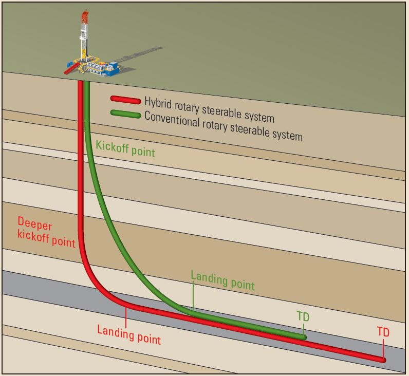
Today, hybrid RSSs use pads inside the tool to push against an internal sleeve that pivots and points the bit in the desired direction. These tools can deliver DLS of up to 18°/30 m. Hybrid RSS tools enable directional drillers to kick off from vertical at greater depths and land, or transition the well to horizontal, more quickly than was previously possible. This technique increases wellbore exposure to the reservoir.
Advanced steering systems use a system-matched mud motor in combination with an RSS tool below it. This BHA design enables higher revolutions per minute at the bit, enhanced steering control and increased rate of penetration.
Future Developments
The introduction of fully automated downhole control systems is likely within the near future. Such advances, however, do not herald the removal of directional drillers from the process; their experience will always be needed to oversee the full scope of directional drilling operations. The future promises to be fast moving and technologically groundbreaking for this highly specialized niche within the oil and gas industry.
Oilfield Review Winter 2013/2014: 25, no. 4.
Copyright © 2014 Schlumberger.
For help in preparation of this article, thanks to Steven Hough, Stonehouse, England; and Richard Hawkins, Midland, Texas USA.