The Defining Series: Overview of Drilling Operations
Published: 08/01/2011

The Defining Series: Overview of Drilling Operations
Published: 08/01/2011
The most recognizable icon of the oil and gas industry is a derrick towering high over the wellsite. The drilling rig represents the culmination of an intensive exploration process; only by drilling a well can a prospect be validated. Once oil companies acquire drilling rights to a prospect, their geoscientists relay potential pay zone coordinates and formation evaluation goals to their drilling engineers, who translate these into drilling targets.
The drilling department plans a trajectory that maximizes wellbore exposure to the pay zones and designs bottomhole assemblies (BHAs) to achieve that course. The engineers prepare a detailed plan for each stage of the drilling process. This drilling prognosis designates a surface location and total depth (TD) for the well and specifies the drill bit size, anticipated mud weights and casing programs needed to reach TD. For deviated wells, it establishes the bottomhole location (BHL) of the well and the initial deflection depth and azimuth for the kickoff point (KOP). The prognosis serves as the basis for a drilling budget set forth in an authorization for expenditure (AFE).
The Drilling Contractor
Oil companies usually hire a drilling company to drill their wells. The drilling contractor provides a drilling rig and crew. These services are typically contracted at a day rate ranging from thousands to hundreds of thousands of dollars per day, depending on the type of rig used.
Onshore, day rates are generally determined by the rated horsepower of a rig, which also dictates how deep the rig can drill. Depth also translates into rig size, with larger rigs carrying a drawworks and derrick with greater hook load capacity for hoisting hundreds of tons of drillpipe. Offshore rigs, also rated by horsepower, are further classified on the basis of operational water depth. Jackup rigs are used in waters from about 9 to 105 m [30 to 350 ft] deep. (Certain heavy-duty jackups can operate in up to 168 m [550 ft] of water and are rated to drill to 10,660 m [35,000 ft].) Semisubmersible rigs are designed for waters exceeding the depth limit of jackups. Drillships operate in the deepest waters. Day rates for onshore rigs are generally lower than for offshore rigs; shallow-water jackup rigs tend to cost less than deepwater semisubmersible rigs or drillships.
Spudding In
The drilling contractor moves the rig onto location and a surveyor certifies its position. As the drilling crew rigs up, sections of large-diameter conductor pipe are welded together and driven into the ground—generally to a point of refusal, where it can be forced no deeper. A wellhead is secured to the top of the conductor pipe.
On the rig floor, the drilling crew makes up the BHA, consisting of a drill bit, drill collars, stabilizers and in some cases, a reamer. The BHA may be augmented with logging-while-drilling (LWD) sensors, a mud motor and a system for steering the drill along its specified trajectory. The BHA can be changed from one section of the well to another to build, hold or drop the angle of wellbore inclination.
Each part of the BHA is designed for a specific role. Drill collars—heavy, thick-walled joints of pipe—provide stiffness and weight to prevent buckling. Stabilizers increase BHA rigidity to prevent vibration and maintain trajectory. In certain formations, specialized reamers are employed to keep the borehole in gauge or enlarge it beyond the bit diameter and help reduce torque and drag. The BHA, in turn, is connected to 31-ft [9.5-m] joints of heavyweight drillpipe that form a transition between the drill collars of the BHA and the standard drillpipe used to make up the drillstring, which drives the bit.
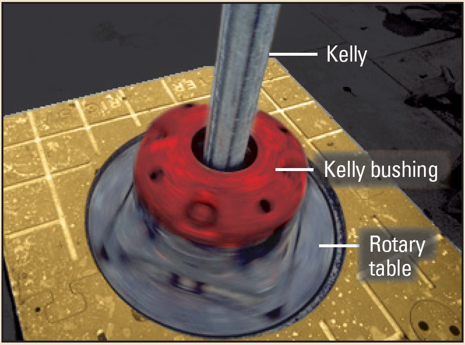
The BHA is lowered through the drill floor, Kelly through the wellhead and into the conductor pipe. Once the bit is on bottom, a kelly bushing hexagonal or square shaped pipe, known as a kelly is screwed into the uppermost joint of drill pipe. The kelly is inserted into the kelly bushing (KB) and the rig's rotary drive is engaged. The rotary table turns the KB, which turns the kelly (Figure 1). The drillstring rotates (turning to the right in a clockwise rotation) and drilling begins. The commencement of drilling is termed spudding in, and, like a birthday, is recorded as the well's spud date.
Drilling Ahead
As the bit bores deeper into the earth, each additional length of drillpipe is connected to the previous joint, and the drillstring grows progressively longer. Drilling fluid or mud, is pumped downhole to cool and lubricate the bit. The mud also carries away rock cuttings created by the bit. Drilling fluids typically consist of a specialized formulation of water or a nonaqueous continuous phase blended with powdered barite and other additives to control the rheology of the mud. (Sometimes water is used in the upper parts of a wellbore; some formation pressures are so low that air can be used instead of mud.)
High-pressure pumps draw the mud from surface tanks and send it down the center of the drillpipe. The mud is discharged through nozzles at the face of the bit. The pump pressure forces the mud upward along the outside of the drillpipe. It reaches the surface through the annular space between the drillpipe and casing, exiting through a flowline above the blowout preventer (BOP). The mud passes over a vibrating mesh screen at the shale shaker; there, formation cuttings are separated from the liquid mud, which falls through the screens to the mud tanks before circulating back into the well.
Drilling fluid is vital for maintaining control of the well. The mud is pumped downhole to offset increases in bottomhole pressure that would otherwise force formation fluids to enter the wellbore, causing a hazardous kick or even a blowout. However, the pressure exerted by the mud must not be so great as to fracture the rock itself, which would lower the pressure of the mud in the wellbore. The pressure exerted by the mud is primarily a function of mud density, which is commonly adjusted by controlling the amount of barite or other weighting agents in the system. Pressure generally increases with depth, so mud weight must also be increased with depth. Drilling typically proceeds until further increases in mud weight would fracture the formation, at which point, casing is set.
Tripping the Bit
The bit's cutting surfaces gradually wear down as they grind away the rock, slowing the rate of penetration (ROP). Eventually, the worn bit must be exchanged for a fresh one. This requires the drilling crew to pull the drillstring, or trip out of the hole. First, the mud is circulated to bring cuttings and gas up to the surface—a process known as circulating bottoms up. Next, the roughnecks disconnect the kelly from the drillstring and latch the uppermost joint of the drillstring to the derrick's elevators—metal clamps used for lifting pipe. The driller controls the drawworks that hoist the elevators up into the derrick.
The drillstring is pulled out of the hole one stand at a time. On most rigs, a stand consists of three joints of drillpipe connected together—some rigs can pull only two-joint stands; others pull four-joint stands, depending on derrick height. Each stand is unscrewed from the drillstring, then lined up vertically in rows, guided by the derrick operator.
The last stand brings the bit to surface. The bit is unscrewed from the BHA and is graded on the basis of wear. A new bit is screwed into the bottom of the BHA, and the process is reversed. The entire process—tripping out and back into the hole—is called a round trip.
Casing Point
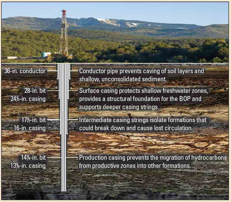
Most wellbores eventually require a means to prevent formation collapse so drilling can continue. Drilling mud, pumped down the hole to exert outward pressure against the borehole wall, is effective only to a point. Then steel casing must be run in the hole and cemented in place to stabilize the wellbore wall (Figure 2).
The driller circulates bottoms up, and the drillpipe is pulled out of the hole. The openhole section is usually evaluated using wireline well logging tools. Once logging is completed, a casing crew runs casing to the bottom of the borehole. The casing, smaller in diameter than the bit, is run in the hole in a process similar to making connections with drillpipe.
Centralizers, installed at regular intervals along the outside of the casing string, ensure proper standoff between casing and formation to allow the passage of cement during subsequent operations. A cement slurry is pumped through the center of the casing string, out through the bottom, then back up the annulus between the casing and the wellbore. Pressure is held on the cement while it hardens.
Leakoff Test
The integrity of the cement job and the formation beneath the casing is evaluated by conducting a leakoff test (LOT). This test is performed immediately after drilling out from under casing to provide a critical estimate of mud weight limits that can be used to drill safely to the next casing point.
After drilling through the cement at the casing shoe and into about 3 to 6 m [10 to 20 ft] of fresh formation, the driller circulates bottoms up to confirm that the bit has penetrated new formation. The well is then shut in and drilling fluid is pumped into the wellbore to gradually increase the pres-sure against the formation. Eventually, the pressure will deviate from a straight-line increase, indicating that the drilling fluid has leaked off, or entered the formation.
The results of the LOT dictate the maximum pressure or mud weight that may be applied downhole during drilling before setting casing once more. The maximum operating pressure is usually set slightly below the leakoff test result to maintain a small safety factor. The overall cycle of drilling, tripping and casing the hole continues until the well reaches TD.
Evolving Technologies
The trend in drilling has evolved from vertical to directional wellbores, and horizontal wells have become quite common, thanks largely to rotary steerable systems. As drilling environments and targets become more challenging, advances in steering and LWD systems are helping drillers change trajectories and stay in zone to reach multiple targets. Wells can be drilled using underbalanced or managed pressure techniques to prevent formation damage. Now, rather than simply punching holes down as quickly as possible, highly skilled crews drill wellbores that will hold up to stresses imposed by the earth and by production processes, providing wells that can be safely logged, completed and produced.
Oilfield Review Autumn 2011: 23, no.
3. Copyright © 2011 Schlumberger.
For help in preparation of this article, thanks to John Walker, Kuala Lumpur, Malaysia.
Autumn 2011