The Defining Series: Gas Lift
Published: 07/29/2016

The Defining Series: Gas Lift
Published: 07/29/2016
Artificial lift systems are designed to help natural reservoir energy power formation fluids to the surface at targeted rates. Gas lift systems aid or increase production by injecting high-pressure gas from the casing annulus into fluids that have entered the production tubing from the formation. The injected gas reduces the fluid density and, thus, the hydrostatic pressure of the fluid, allowing in situ reservoir pressure to lift the lightened liquids.
The technical applicability and economic viability of gas lift installations are determined by two factors: gas availability and compression costs. In the majority of gas lift wells, nearby wells produce enough gas to supply the system, and after the fluids have been lifted to the surface, the gas can be separated from the liquids and returned to the casing annulus to maintain required gas volume and pressure. When circumstances permit, the industry also uses natural, or auto, gas lift systems, which is highly cost effective because it eliminates the need for compressors, pipelines or a separate source of natural gas.
System design
Engineers design gas lift systems by first calculating the production potential of each well in the network. Then, based on available gas pressure and volume, they assign each well its optimum production rate and gas lift allocation.
An ideal gas lift system is one in which gas is injected into the fluid column at a continuous rate and at a constant pressure. This process ensures a stable liquid flow rate from the reservoir and is possible only in fields in which sufficient volumes of high-pressure gas are available and liquids can flow easily through the formation to the wellbore.
Engineers must also construct wells to accommodate the type of injection system to be used. Gas may be injected into the fluid column through an open system that has no seal between the tubing and casing annulus or uses a standing valve in the tubing to isolate the casing annulus from the production tubing. However, the most common gas lift well configuration includes a packer and gas lift valves.
Designing a gas lift system that optimizes production is a complex challenge. Engineers must account for the interaction of all parts of the production system; the potential, constraints and needs of each well must be considered individually along with those of the network as a whole. Flowline and downhole tubular sizes and lengths, processing equipment, gas and compressor availability, fluid composition and other factors impact gas lift efficiency and production.
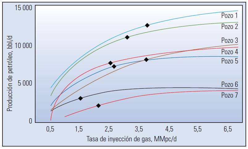
Today, designers may address these complex calculations using optimization software programs that model the production network (Figure 1). These programs allow the engineer to optimize the system based on a field economic driver such as total liquid production, total gas produced or total oil produced and to test the effects of various injection rates.
Because field and individual well conditions are constantly changing, operators may mate computer optimizing capabilities to real-time data. They can then adjust injection rates to match changing conditions and quickly identify and take steps to correct underperforming wells or gas lift systems.
Figure 1: Gas lift optimization. Every well in a field or network of wells has an optimal gas lift operating point (black diamonds) at which it will produce the most fluid. Using gas lift optimization software helps system designers set an optimal injection gas rate for each well across the network of wells. Rates are based on gas availability and formation fluid production potential. Optimal production for each well in a network therefore may be lower than its potential.
Gas lift valves
Gas lift valves are the means by which operators adjust the rate of gas injection into the liquid column in the production tubing. Check valves within the gas lift valves allow flow in only one direction— from the casing annulus into the production tubing. For maximum efficiency, gas lift valves are staged as deeply in the well as possible; setting depth is limited by available injection pressure. Injection pressure-operated gas lift valves are designed to open typically in reaction to a specified gas pressure in the casing annulus.
Gas lift valves may also be placed at various depths between the bottom-most valve and the surface. These valves are used primarily at the start of production to reduce the density of the fluid that has risen above the primary point of gas injection at the deepest set valve. This process is referred to as well kickoff or well unloading. Typically, the operating valve is the bottommost valve.
Production pressure-operated gas lift valves, placed at various depths in the well, may open in response to a preset level of pressure exerted by the produced fluid column. They remain closed unless the well experiences an increase in fluid in the tubing, at which point they open to assist in lifting the excess fluid from the well.
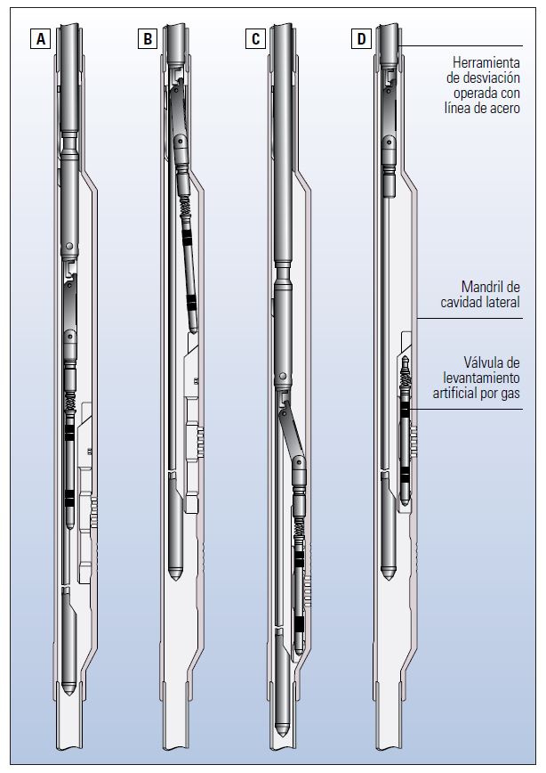
Engineers set conventional gas lift valves in mandrels that are part of the tubing string; such valves may be retrieved only by pulling the tubing string. Valves may also be placed in side pocket mandrels, which provide communication between the annulus and the production tubing and a locking mechanism to hold the valve in place. These valves may be set in and retrieved from the mandrels via slickline or coiled tubing tools (Figure 2).
Seals on the valve are matched to a polished bore on the inner wall of the mandrel; the seal and the polished bore create an isolated pathway for the gas to flow through the valve and out into the production string. Gas exits the valve through an orifice that is sized to produce the desired gas flow rate into the production tubing. To obtain the steady and constant fluid flow rates that are essential to an optimized gas lift system, the gas must enter the production string at critical velocity.
Critical velocity is generally defined as the minimum gas velocity in the production tubing required to move fluid droplets upward. Below the critical velocity, droplets fall, and liquids accumulate in the wellbore. In addition, when the rate falls below critical flow, small changes in downstream pressures can cause large changes in flow rate that the system may interpret as a need for more gas, which may lead to oscillations in pressure and production rates. Above critical flow, the system cannot detect changes in flow downstream of the valve thus will not respond to the situation by increasing gas flow.
Figure 2: Setting and retrieving gas lift valves. Gas lift valves are run into the well and set in side pocket mandrels using a slickline or coiled tubing tool attached to a kickover tool. The kickover tool contains a spring mechanism, which is locked into place while the valve is being run into the well. The slickline or coiled tubing operator runs the tool past the side pocket mandrel (A) and then reverses direction (B), which unlocks the spring. When the bottom of the valve is pulled across the mandrel opening, the spring forces it into the opening. The operator then reverses direction again and the valve is lowered into the mandrel (C). The operator then pulls upward, which locks the valve in place and releases the setting tool from the valve (D). The operator can reverse the process to retrieve the valve using a gas lift valve pulling tool attached to the kickover tool.
Variations
Gas lift systems are either continuous or intermittent flow. The majority of wells use continuous flow gas lift because it supplements in situ gas, which results in a natural, steady flow of formation fluids to the surface. Continuous gas injection requires a reliable source of high-pressure gas throughout the life of the well. However, in many cases, in situ gas sources decline before the zone is fully drained, forcing operators to turn to an outside source to maintain lift volume.
Intermittent flow gas lift periodically injects gas into the production string to displace slugs of fluid. The high-pressure gas expands rapidly after entering the tubing, which forces the fluid to the surface. In contrast to the steady flow created by continuous flow gas lift, intermittent flow results in slug flow, which may cause gas-and fluid-handling difficulties on the surface. In addition, the extreme pressure changes caused by the sudden injection of gas into the production tubing creates pressure surges near the producing zone, which may cause the onset of sand production in some formations.
Experts recommend the application of continuous flow gas lift for high-volume wells that have high-static bottomhole pressures (BHPs) and offshore wells that have strong waterdrive or for formations being produced via water-flood that have a high productivity index (PI) and high gas/oil ratios (GORs). Intermittent flow gas lift systems are typically not recommended for wells producing more than about 30 m3/d [200 bbl/d] or in wells that have high BHP but low PI or low BHP and high PI. As a consequence, many intermittent flow systems are deployed in depleted wells that were first using continuous flow systems and on gas wells that have begun to produce water.
Auto gas lift systems, also referred to as natural or in situ gas lift, have specific requirements and thus are used less commonly than traditional systems. Instead of using gas pumped down the casing annulus, these systems are supplied by reservoir gas caps or noncontiguous gas-bearing formations. Completion engineers design auto gas lift wells to include a completion design across the gas cap or gas zone that allows gas to be flowed into the production tubing. Operators control the gas flow rate with a specifically designed auto gas lift valve that has a flow area that can be adjusted from the surface.
Operators may use an auto gas lift system in the same way they would a more traditional continuous or intermittent system. But, because they eliminate certain equipment requirements, auto systems provide an advantage in capital savings and reduce weight on offshore platforms by eliminating the need for a compressor. Auto gas lift systems also allow the operator to produce associated gas without recompleting the well. And, because orifice openings in auto gas lift valves can be adjusted remotely, operators can control gas injection rates to accommodate changes in formation liquids production without an intervention.
The case for gas lift
Gas lift systems offer several benefits not available in other artificial lift systems. Gas lift valves set in side pocket mandrels may be easily and inexpensively removed and be replaced without a workover rig.
Gas lift side pocket mandrels are situated such that the pockets containing the valves are offset from the centerline of the tubing, which keeps the gas lift valves from the fluid flow and thus protects them from solids. Consequently, gas lift technology is a good option for hydraulically fractured wells or for wells completed in unconsolidated formations that routinely produce sand. Gas lift systems are applicable in high-angle, low-productivity and high-GOR wells.
Intermittent gas lift systems can also operate efficiently in low-pressure, low-productivity wells. As a consequence, to capture final production at the end of a well's life, operators may replace other artificial lift systems with gas lift systems until the bottomhole pressure becomes too low to lift the target fluid volumes, at which point operators typically switch AL systems to rod pump or electrical submersible pump systems.
Gas lift is an important artificial lift technique. When a reliable source of gas is available, gas lift systems, which are highly reliable, flexible and robust, can operate for the life of the well. The ability to change valves allows operators to adapt to production changes over the life of the well. As a consequence, gas lift is often the artificial lift method of choice for use in deepwater subsea wells in which continuous operation in high-pressure, high-flow-rate wells is critical.
Oilfield Review 2015.
Copyright © 2015 Schlumberger.
For help in preparation of this article, thanks to Jason Jones, Tyler, Texas, USA, and Eric Lovie, Singapore.