The Defining Series: Geomechanics | SLB

The Defining Series: Geomechanics

Published: 11/09/2015

Grey rock texture

Geomechanics is the study of how soils and rocks deform, sometimes to failure, in response to changes of stress, pressure, temperature and other environmental parameters. In the petroleum industry, geomechanics tends to focus on rocks, but the distinction becomes blurred because unconsolidated rocks can behave like soils. Geomechanics is relatively young as a science and even younger in its application to the petroleum industry. However, it applies to nearly all aspects of petroleum extraction from exploration to production to abandonment and across all scales, from as small as the action of individual cutters on a poly-crystalline diamond compact (PDC) bit through drilling wells and perforating to as large as modeling fields and basins. Over the last 30 years, geomechanics has come to play an increasingly important role in drilling, completion and production operations. This trend continues as operators pursue oil and gas production from shales, in which mechanical anisotropy—the variation of mechanical properties with orientation—plays a vital role.

At the wellbore scale, geomechanics is central to understanding how drill bits remove rock, characterizing borehole stability, predicting the stability of perforation tunnels and designing and monitoring hydraulic fracturing stimulation programs. At the reservoir scale, geomechanics helps model fluid movement and predict how fluid removal or injection leads to changes in permeability, fluid pressure and in situ rock stresses that can have significant effects on reservoir performance. Engineers use geomechanical modeling to predict and quantify these effects for life-of-reservoir decisions such as placing and completing new wells, enhancing and sustaining production, minimizing risk and making new investments.

Choosing the correct bit type and design for optimal rate of penetration and bit life is vital for drilling cost-effective wells. The geomechanics of rock destruction under the drill bit is complex because of high strain rates and temperatures, multiple deformation mechanisms and interactions between the bit, drilling fluid and formation. Many ad hoc approaches to understanding and improving drillbit performance have been taken, and interpretation methods such as mechanical specific energy—the energy used to remove a unit volume of rock—have been used since the 1960s to relate drilling performance to rock strength. Recent advances in research methods related to geomechanics are starting to reveal in more detail the factors, such as the balance between crushing, disaggregation and brittle cracking or chipping,that control the loads on the cutter, its wear behavior and the nature of the rock debris (Figure 1).

Figure 1: Cutting rock. The action of a PDC cutter plowing through sandstone (orange) is shown in a cross section that was imaged using microCT scanning. The location and direction of movement of the tungsten carbide (gray) and diamond (black) cutter are shown schematically. The section displays the deformation—crushing, disaggregation and brittle cracking—induced by the cutter.

The action of a PDC cutter plowing through sandstone (orange) is shown in a cross section that was imaged using microCT scanning.

Geomechanics also plays a major role in understanding the stability and integrity of the borehole while drilling. The presence of the wellbore and the pressure of the drilling fluid induce changes in the stress state or in the rock. As a result, the rock around the borehole may fail if the redistributed stresses are greater than the rock strength. Tensile cracking occurs if the mud pressure becomes too high and causes the borehole wall to go into tension. Breakouts, which occur if the mud pressure becomes too low, are regions of enlargement on opposing sides of a borehole, where shear cracking has occurred and the broken rock has been removed by the bit, stabilizers or mud flow. These failures can lead to stuck pipe, lost circulation and other drilling problems but can also be a valuable source of information about stress magnitudes and orientations.

By computing the stress changes around a planned borehole and comparing them to the strength of the rock, engineers can generate a mud weight program for the well. Typically, the mud weight must be high enough to suppress shear failure and fluid influx and low enough to avoid tensile failure and lost circulation. Although the mathematical techniques for calculating the stresses and the failure criteria are established and routine, the links between rock failure and drilling problems are not so well established. Furthermore, some additional failure modes, such as bedding plane failure, cannot yet be reliably predicted (Figure 2). Consequently, effective wellbore stability control, especially along challenging well trajectories, needs real-time monitoring of wellbore conditions as well as predrill prediction of the required mud pressure program.

Figure 2: Unpredictable wellbore failure. A laboratory model shows bedding plane failure in a hole drilled parallel to bedding in a fissile shale. The stress applied to the sample is the same in all directions, in spite of the directionality of the failure. This geometry is similar to the geometry of failures observed in the roofs of mines in fissile rocks, although the driving force in mines is gravity rather than in situ stress. The borehole pressure needed to prevent this type of rock failure cannot currently be reliably estimated.

A laboratory model shows bedding plane failure in a hole drilled parallel to bedding in a fissile shale.

A challenge for geomechanics modeling and prediction is the availability of input data—primarily rock strength and in situ stresses. Rock strength is easily measured on core samples in the laboratory, but the process is time-consuming and costly, and the results usually help with future wells rather than the current one. Consequently, considerable effort is spent deriving rock strength values from wireline, LWD and sonic data. The trade-off is less accuracy but higher spatial coverage along the well than is available from core data.

These data are interpolated or extrapolated to cover sections of interest in new wells or are used to improve predictions for the current well. The same data may also be used in geologic burial history models for constructing vertical profiles of the in situ stresses, which then are compared with and calibrated to discrete stress measurements in a well. More recently, advanced sonic tools have allowed estimation of rock strength and some components of the in situ stress for input into geomechanics models.

Events such as induced seismicity in the 1970s at the Rangely field, Colorado, USA, and compaction and subsidence in the 1980s at the Ekofisk field, North Sea, offshore Norway, helped engineers realize the role of geomechanics at the reservoir scale. Examining geomechanical changes on this scale is routine now, thanks to the development of finite element analysis programs that have been optimized for geologic structures and rock mechanical behavior (Figure 3). Populating these models with rock data can be a challenge, but since the computation grid is coarse, it can be done using seismic data. Once the model is populated, the mechanical response of the reservoir and overburden can be estimated for a variety of operations—including production, injection and fracturing. The model can be calibrated or refined with repeat, time-lapse seismic surveys and the addition of data as new wells are drilled. Operators can use this type of information to estimate the injection pressure used in fracture stimulations that risk a breach in a reservoir seal, or they can predict the fracture gradient after a period of production, allowing safe and effective drilling of infill wells.

Figure 3: Coupled simulation. A geomechanics model of a reservoir (background) is shown with the seismic dataset (left) used to build it. Data for refinement of the model were acquired from several wells (colored lines), which were used to model changes over time from events such as depletion. Several faults (colored planes) and the top of the reservoir unit of interest (brown surface) are shown. The edges are the model boundaries or are reservoir discontinuities caused by faults.

A geomechanics model of a reservoir (background) is shown with the seismic dataset (left) used to build it.

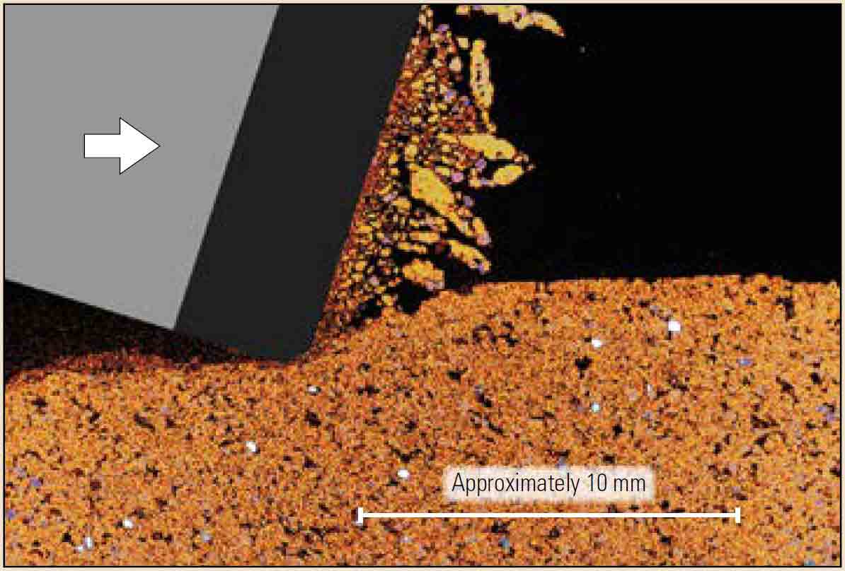
Reservoir stimulation by fracturing, one of the first applications in the oil field to use geomechanics methods, is still a major development area. Exploitation of shale reservoirs has caused a surge of interest in the mechanical anisotropy of rock, which was not widely appreciated until about 2000. To make improved predictions of fracture geometry and growth, models for stress and strength and interpretations of sonic and resistivity measurements must be modified to account for anisotropy. Advances in sonic logging tools and interpretation have made this possible.

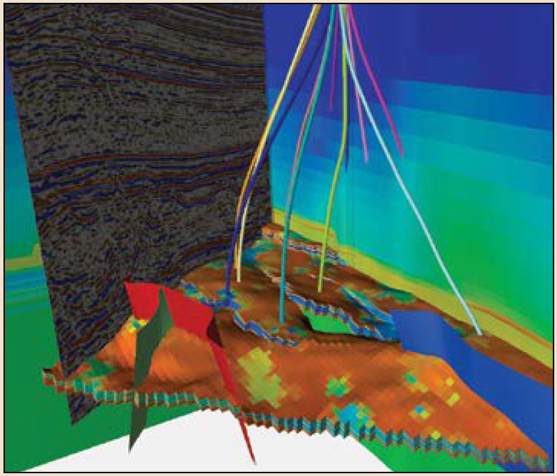
One feature common to all of these areas is the mechanical earth model (MEM), which is a collection of the data needed to make quantitative and qualitative predictions of the subsurface geomechanical environment. These data include the stresses in the Earth, pore pressure, rock elastic properties, strength and fabric and nonnumerical data such as the presence of intense natural fracturing. An MEM can be simple or complex, be large or small and be 1D, 2D, 3D or 4D—three spatial dimensions plus time—according to the complexity of the field and phenomena of interest. The most important defining feature of an MEM is that its data are related to the rocks that are being drilled, fractured or otherwise affected by field operations, rather than a particular well or set of wells. A second feature is that it is designed to be updated as new data become available from ongoing operations. Data sources for an MEM include any that give information on stress and mechanical behavior; such sources include wireline and LWD logs, cores, cavings and cuttings, regional geology and all types of seismicity.

Ongoing challenges for geomechanics include improvements to

  • sources of data for predicting in situ stress and rock properties
  • the use of anisotropic information for predicting deformation during exploitation of unconventional resources
  • the treatment of fault and fracture displacements within numerical models.

In addition, to help improve the application of geomechanics to various sec-tors in the industry, engineers must have a better understanding of the relationships between rock failure and operational failure for wellbore instability and sand production.

Geomechanics in the oil field has come a long way from its early days as an adjunct to sonic logging. It is recognized as an important part of nearly all aspects of petroleum extraction and has been crucial in improving efficiency and driving down costs. The application of geomechanics in new reservoir types and mature ones and its integration into operators' workflows, along with the introduction of new measurements and techniques, will ensure its continuing role in the industry. From here, its operational impact will only grow. The application of geomechanics for revitalizing mature fields is imperative and will affect activities such as infill drilling, compaction mitigation and refracturing.

Byline
John Cook, Scientific Advisor
Publication
Oilfield Review
Article Topics
Geomechanics
Products Used