The Defining Series: Intelligent Completions
Published: 06/15/2016

The Defining Series: Intelligent Completions
Published: 06/15/2016
Because they took place in relatively shallow waters, early offshore exploration and production operations were similar in many ways to those taking place onshore. However, by the 1980s, operators were drilling for resources found in remote areas and far from land in water depths that exceeded 300 m [1,000 ft]. To tap deepwater discoveries that can extend over many square kilometers, operators drill wells from floating drilling units; these wells may extend laterally thousands of meters.
To reduce the number of platforms required to exploit a field, operators use subsea completions for most wells completed in deep water. Subsea completions are remotely controlled and accessed through wellheads that rest on the seafloor. Production flows from subsea wellheads and through flowlines on the ocean floor to a central surface processing unit.
What may be considered minor downhole operations on land and in shallow water are often extremely costly when carried out on these wells located in deep water where interventions require the use of floating rigs. Faced with the specter of maintenance costs and production delays large enough to upend well economics, the industry sought completion strategies that would minimize well interventions. Central to those efforts was refinement of downhole monitoring and control systems, which were standardized and packaged as intelligent completions (ICs). Intelligent completions include pressure and temperature sensors that are able to deliver measurements to the surface in near real time and remotely adjustable downhole chokes and sliding sleeves with which engineers can, from the surface, control flow at the formation. Chokes are devices that control and regulate fluid flow; sliding sleeves are downhole hardware that can be opened or closed to manage fluid flow into the well.
Because ICs were complex and expensive, operators limited their use almost exclusively to high-rate subsea wells. Over time, however, systems became less costly and were integrated with software that enhanced their capabilities. Software designed for use in IC planning and management emerged at roughly the same time as did drilling technologies that allowed operators to drill long high-angle and multilateral wells that could access numerous production zones from a single main wellbore.
Zonal Isolation
The ability to simultaneously access and isolate numerous zones connected to a main bore is an essential feature of ICs. In basic vertical wells that have two or three producing formations, completion designers may accomplish this by deploying a dedicated tubing string for each zone. In wells that have many producing intervals, operators set packers above and below each target zone. Packers use elastomer elements that expand to create a seal against the wellbore.
Operators use feed-through packers to isolate zones in ICs. These packers have penetrations through which electrical cables and hydraulic lines can be passed without compromising the seal. The lines passed through the packer are attached to the devices and sensors that control and monitor flow at each zone.
Flow Control
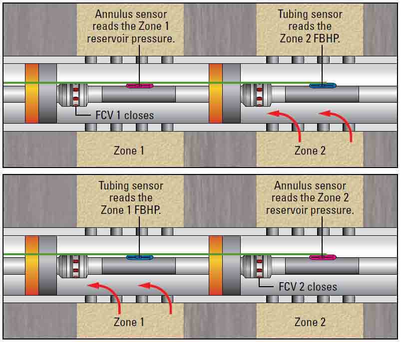
To control flow from the formation, well operators may remotely open, close or adjust the choke setting of downhole valves. The on-off option allows operators to shut off production from a zone from which they may wish to delay production, has become depleted or begins to produce unwanted gas or water. In addition, by closing all but one zone and monitoring a pressure gauge at the sandface, operators can replicate much of the information that is available from wireline production logs (Figure 1).
Figure 1. Production log-type data without intervention. In a multizone IC, each zone is isolated, monitored and controlled. The flowing bottomhole pressure (FBHP) may be measured as flow from Zone 2 (red arrows) by closing the flow control valve (FCV) across Zone 1 (top), while reservoir buildup pressures in the shut-in Zone 1 are measured. By closing the FCV across Zone 2 and opening Zone 1 (bottom), reservoir pressure may be determined in Zone 2 and FBHP from Zone 1. This technique may be applied to any number of zones.
Additional downhole flow control valves allow operators to regulate flow rates at the sandface. Changing choke settings by varying the size of the valve flow port, production engineers can control the pressure and volume contribution from a formation without shutting it off. This feature allows operators to commingle production from differently pressured zones without creating crossflow, in which flow from a higher-pressured zone flows into a zone of lower pressure.
By varying choke sizes at the sandface, engineers can also change the relative contribution of each zone to overall well production. This ability allows operators to optimize production over time as individual zones experience changes in rate, pressure, gas/oil ratio or water/oil ratio. Changing flow rates from individual zones allows operators to reduce drawdown pressures at specific points in the reservoir and thus control water and gas coning. Coning is the unwanted preferential flow of water or gas that results from pressure drawdown at a perforated interval. Engineers can also optimize sweep efficiency by using adjustable flow valves to increase or decrease gas or water injection rates at targeted intervals.
Operators may place flow control valves at multilateral well junctions, where the main wellbore and high-angle and horizontal wellbores, or laterals, drilled from it are joined. To optimize production from each lateral, engineers equip the lateral production liner with inflow control devices (ICDs), which create increased backpressure as flow velocity through them increases. By exerting backpressure at intervals along the liner that is inversely proportional to fluid velocity, ICDs hinder the flow of high-pressure fluids or fluids flowing through highly permeable strings within an interval. This allows fluids from lower-pressured or less-permeable intervals to flow into the lateral wellbore. In addition, ICDs are used in oil wells to reduce water and gas flow rates in lateral wells when these phases are able to flow through the formation more easily than does the oil.
Monitoring
Effective flow control is only possible when used in conjunction with permanent downhole gauges that are able to accurately monitor production variables in real time. In recent years, the ability to gather pressure and temperature measurements at the formation and transmit them to the surface in real time, along with greatly increased sensor longevity and reliability, has changed the role of ICs from intervention avoidance to reservoir management tool.
Unlike earlier pressure-temperature gauges that remained downhole for a few hours or days, modern downhole permanent pressure and temperature gauges are designed for long-term deployment. Rated to work in pressures and temperatures as high as 172 MPa [25,000 psi] and 180ºC [356ºF], they derive their longevity and reliability from the use of quartz and sapphire transducers, welded assemblies, corrosion-resistant alloys and durable electronic components.
Because data obtained from permanent downhole gauges are acquired over an extended period of time, engineers are able to use them as a means for gathering insight into the reservoir. Monitoring systems have been designed that also measure flow rate and fluid density. These measurements can be used in pressure transient analysis to estimate the permeability, skin and drainage area over the life of the well. Skin is an estimation of flow efficiency; positive skin values refer to reduced flow compared to that from an undamaged formation. Engineers can use that data to identify production and reservoir anomalies such as water and gas breakthrough.
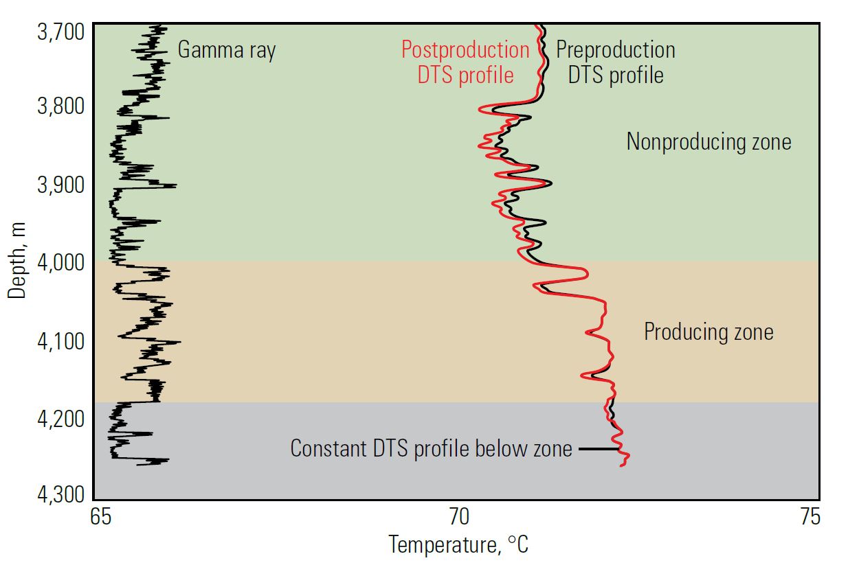
Operators may use fiber-optic cables deployed along the length of the production tubing to monitor downhole conditions. These distributed temperature sensors (DTSs) provide data that may be analyzed to quantify inflow profiles along the entire length of the well, allowing operators to immediately see, understand and react to changes in flow patterns from individual zones (Figure 2).
Figure 2. Distributed temperature sensor (DTS) profile. Changes in temperature profiles along the length of a well are caused by commingled flow from multiple zones. By comparing flowing temperature profiles captured using permanent fiber-optic DTSs over time and correlated to a gamma ray log, operators are able to detect the origin and cause of changes to that profile. In this instance, deviation between the original DTS profile above the monitored zone (green shading) and the later DTS profile can be clearly traced to the zone defined by the gamma ray log (tan shading) because the profile becomes constant below the producing zone (gray shading).
Well Design
Because intelligent wells include complex assemblies, engineers typically rely on computer programs to help them select, coordinate and manage them. These software programs allow designers to import wellbore and trajectory information into modeling programs that are used to create and analyze various casing and tubing designs. Available reservoir—data such as number and depths of zones, oil and gas gravities, hydrocarbon composition, initial and final reservoir pressures and productivity indexes—are used as input for production modeling.
Using production models, operators are able to calculate total flow rate and production contribution from each zone. They can then add restraints to the design, such as the number of control lines available or the number of zones to be produced, and choose the well design and production scenario that optimizes hydrocarbon recovery. By varying choke settings within the model, the operator can observe the impact on individual zonal contribution and overall production and customize flow control valve settings before the wells are completed.
To maximize the benefits of real-time downhole monitoring and control capabilities, operators must process and act on a significant volume of data throughout the life of the well. To accomplish this, downhole data are sent to operator offices through supervisory control and data acquisition (SCADA) systems, where they are analyzed using production optimization software. A steady-state, multiphase flow simulator uses modeling algorithms for nodal analysis to compare the data with those expected from optimal settings and take corrective actions such as changing choke settings and flow rates at one or more intervals.
In some advanced systems, the operator inputs a target production rate or other parameters such as water production levels, and the program adjusts the down-hole chokes to achieve the desired result. The target parameter may be set for a zone, well or entire field. Software programs designed for intelligent well control and monitoring may be expanded fieldwide to notify operators of equipment performance deviations or to capture production trends in the field over time.
Refining the System
As a consequence of the development of more precise remote monitoring, control capabilities and design and management software, operators now deploy ICs in a variety of well types, not only to minimize interventions but also to optimize operating efficiency and production. At the same time, the E&P industry is shifting from analog to digital data recording, providing operators with a tool for integrating and processing large amounts of data from many sources. The ability to treat these data from a fieldwide perspective has been critical in allowing operators to realize the full potential of ICs and, by extension, the reservoirs the completions are designed to access.
The latest iteration of IC systems includes in situ measurements of pressure, temperature, flow rate and water cut across the formation face in each zone of each lateral. All sensors are packaged in a single station together with an electric flow control valve that has infinitely variable settings controlled from the surface through a single electric control line. This ability to monitor and control large numbers of zones in a well has significantly increased operator production and reservoir management in heterogeneous or multilayered reservoirs and in extended-reach developments.
Oilfield Review 2016.
Copyright © 2016 Schlumberger.
For help in preparation of this article, thanks to Adrian Francis, Houston, Texas, USA.