The Defining Series: Reservoir Drive Mechanisms

The Defining Series: Reservoir Drive Mechanisms
Producing hydrocarbons, bringing them from downhole reservoirs to the surface, in an efficient and cost effective manner can be a challenge for E&P companies. In order to efficiently produce those hydrocarbons, reservoir engineers must understand the reservoir drive—the mechanism that moves hydrocarbons out of the rock pore spaces and into the wellbore. Understanding a field's active drive system or systems helps operators develop production strategies that maximize the recovery factor—the percentage of oil or gas that is brought to the surface compared with what was originally in place.
Reservoir Energy
Reservoir fluids in their virgin state have been affected by numerous natural forces. The overburden—layers of rock and soil above a reservoir—weighs upon the rocks and fluids and affects temperature and pressure within the reservoir. Over geologic time, forces in the reservoir equilibrate and establish the formation pore pressure, which is the primary energy source for moving fluids through a formation. In a permeable formation with no barriers such as shale layers or faults to block their movement, fluids can migrate through the rock. Gravity will cause fluids to segregate according to fluid density, such that the typical order of fluids in a reservoir is gas on top, oil and then water at the bottom.
If pressure disequilibrium occurs, fluids will move from regions of high pressure to those of low pressure. After a well has been drilled and completed, the wellbore can create disequilibrium, serving as a low pressure conduit toward which fluids in the wellbore will migrate.
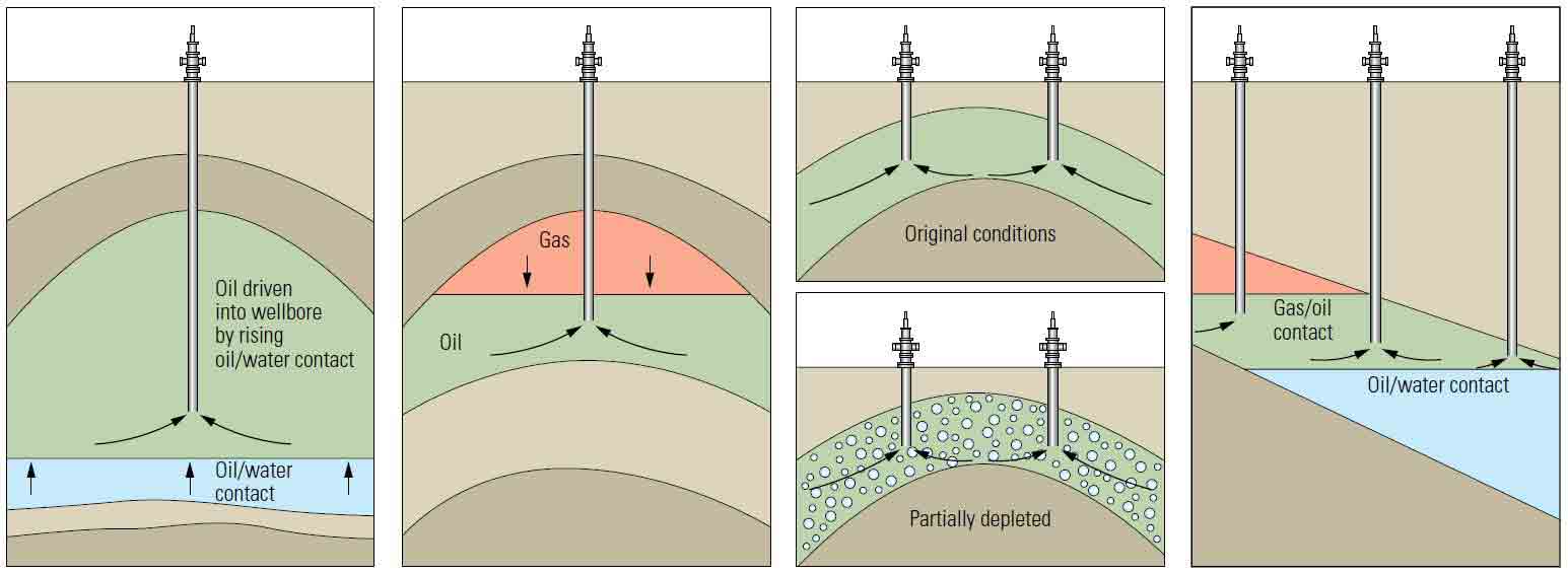
As oil, gas and water flow into a wellbore, the pressure equilibrium is disturbed near the well. In order to preserve or restore the equilibrium, fluids flowing into the well are replaced by fluids from farther away. Fluid movement depends on fluid properties such as density and viscosity and rock properties such as wettability and capillary pressure. Because of rock and fluid heterogeneity, fluids may not move uniformly throughout the reservoir. In addition to rock and fluid properties, drive mechanisms—which describe the source of energy for moving fluids into, through and out of a reservoir—also determine how fluids move within the reservoir. The primary natural drive systems are water drive, solution-gas drive, gas-cap drive and gravity drive (Figure 1). Combination drive systems are common and are mixtures of two or more primary drive systems. Although another drive mechanism—rock compaction drive—is rare, it is an important factor in a few major fields around the world.
Drive Mechanisms
The energy for a waterdrive system comes from a connected aquifer. As hydrocarbons are extracted, the aquifer expands, and water migrates to replace the moved oil or gas. This water may come from below, a bottomwater drive, or it may come from surrounding sources, an edgewater drive. If the aquifer encircles the producing reservoir, it is referred to as a peripheral edgewater drive.
As hydrocarbons are produced in a bottomwater drive, the contact between oil and water (OWC) or gas and water (GWC) moves upward. As the contact rises, water may reach the producing interval in the well. Accelerated movement caused by large pressure differentials around the wellbore may cause water near the well to rise faster. This phenomenon—referred to as coning—can cause early water production from high flowrate wells (Figure 2). Formation water in edgewater drive systems will encroach on producing wells and eventually break through, or reach the well. Because of formation heterogeneities, the water may move nonuniformly, or finger, through the reservoir, resulting in early breakthrough of water production in the most permeable zones.
Figure 2. Coning in a waterdrive system. To reestablish pressure equilibrium, produced oil is replaced by fluids from elsewhere in the reservoir. High flowrate wells may impart a nonuniform pressure gradient in the reservoir and cause water to flow toward the producing well. This flow toward the pressure sink may create an inverted cone of water.

If the aquifer is large, the influx of water may be sufficient to maintain reservoir pressure for a long time. A common secondary recovery technique based on the waterdrive mechanism is waterflood, in which operators inject water into oil reservoirs to sweep oil toward producing wells, replace extracted fluids and support reservoir pressure. Eventually the water cut—the ratio of water produced compared with the total volume of fluids produced—will reach a point where the cost of water disposal exceeds the commercial value of the hydrocarbons produced. Within a field having periphery edgewater drive, producing wells on the edge of the field will be the first to experience water breakthrough and may be shut in or converted to waterflood injector wells to enhance recovery. Waterdrive systems are efficient and have recovery factors that can range from 35% to 75% of the original oil in place (OOIP). The average recovery factor is around 40%.
The energy source for gas cap drives comes from expansion of the gas at the top of the reservoir. The gas may be in place when the reservoir is initially produced, a primary gas cap, or it may form as a secondary gas cap, which results from gas migration out of the oil when reservoir pressure drops below the bubblepoint. The bubblepoint is the pressure and temperature at which bubbles of gas first begin to evolve from oil that has gas in solution. Gas expands as the pressure in the reservoir drops, occupying the pore volume that once contained liquids. The stored mechanical energy in the gas is released as it expands, which helps maintain reservoir pressure.
To avoid producing gas from the cap, wells are completed across the oil column, referred to as the oil leg. The gas/oil contact (GOC) will move downward as oil is produced and the cap expands. The gas that forms the gas cap must not be produced or the pressure in the reservoir will drop rapidly; a sudden breakthrough of gas indicates that the GOC has dropped below the topmost perforated interval in a well. Produced gas from the field may be injected back into the cap for pressure management and to support further expansion. Gas cap drive system recoveries can range from 20% to 40% of the OOIP. The average recovery factor is around 30%.
Solution gas drives are found in saturated reservoirs, in which the ini-tial pore pressure is above the bubblepoint. As oil is produced, the reservoir pressure drops below the bubblepoint, gas bubbles come out of solution and expand in the oil. Solution gas can also be liberated from water. The expanding gas bubbles add energy to the system and support reservoir pressure. Gas bubbles in the oil may help reduce the viscosity of the oil and thus facilitate flow of the oil from the reservoir into the wellbore, although after the bubblepoint has been reached, oil production usually declines and gas production increases (Figure 3).
Figure 3. Typical performance from a solution gas drive system. At the initial production with a solution-drive mechanism, the well produces oil (green) with a low gas/oil ratio (GOR) (blue). As oil is extracted, the reservoir pressure (black) drops, gas comes out of solution, and the GOR rises sharply; consequently, oil production drops.

As the reservoir pressure in a solution-gas system falls, liberated gas may migrate to the top of the reservoir, producing a secondary gas cap. If the oil is produced rapidly, gas bubbles may form and expand in the pores of the rocks, which can impede oil flow through the reservoir. As with a primary gas cap, depleting the secondary gas cap can cause rapid pressure decrease and reduce recovery. Solution gas drive system recovery factors range from 5% to 30% of the OOIP. The average recovery factor is around 15%.
Gravity drives are found in reservoirs that have both gas cap and water drives; these types of reservoirs can be very effective producers. The energy comes from two directions: upward from the hydrostatic pressure in the oil column and downward from an expanding gas cap. This reservoir drive mechanism may also be referred to as combination drive. For many oil reservoirs, the production of fluids is controlled by more than one drive mechanism, and reservoir engineers use the term combination drive to describe them. Gravity drive system recovery factors range from 5% to 85% of the OOIP. The average recovery factor is around 50%. Producing slowly from formations with these drive mechanisms may greatly improve ultimate recovery.
The rock matrix in some reservoirs contracts as fluids are produced. This contributes energy to the system and is referred to as compaction drive. Although compaction drives are rare, the presence of compaction improves recovery factors compared to the recovery rates from formations that don't contract from production. These reservoirs frequently have solution gas, water or gas cap drive mechanisms.
Consequences of Drive Mechanisms
Reservoir engineers study downhole conditions to optimize completion strategies. After production begins, they monitor the changing conditions to avoid situations that could negatively impact reservoir performance and recovery factors. Reservoir management may involve avoiding early onset water breakthrough and coning, pressure management to avoid dropping below the bubblepoint pressure, higher gas production in solution drive systems and patience with gravity drainage systems to allow fluids to equilibrate.
Eventually, primary recovery mechanisms become ineffective, and reservoir engineers may turn to enhanced recovery techniques to extend the life of producing fields. During primary production, secondary recovery techniques such as waterflood and gas reinjection, may improve recovery, improve economic viability and extend the life of a reservoir. Proper reservoir management can help operators increase recovery and improve asset performance.