MA20 Series
Pneumatic diaphragm actuators

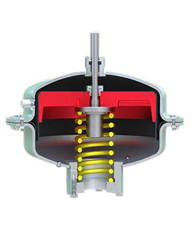
Our line of Saf-T-Gard actuators includes MA20 Series diaphragm actuators, which incorporate features from our field-proven products, combined with our industry-leading, innovative technology. Particular attention has been given to safety, ease of maintenance, and cost of manufacturing. The Cameron pneumatic diaphragm actuator series can be used with all manufacturers' gate valves in nominal sizes from 2 to 6 in.
The MA20 Series doubles the area affected by applied control pressure. Its simple design and operating principle make this diaphragm actuator inherently trouble-free, avoiding most of the problems such as galling misalignment, distortion, and O-ring failures commonly associated with piston-type actuators. The Saf-T-Gard diaphragm actuators are interchangeable with other models in the product line, which reduces the number of spare parts typically required for maintenance.
Advantages
- Stronger actuator mounting arrangement
- Corrosion-resistant materials
- Superior diaphragm design
- Flexible actuator orientation
- Rapid closure
- Heavy-duty compression spring
- Simplified seal replacement
- Actuator interchangeability
- Fixed drift adjustment
- Cameron seal technology
Specifications
- Model: MA20
- Series: 2000
- Specific application sizing: 1 13/16 through 8 in
- API Specs 6A and 6D
- Standard trim: AA
- PSL 1, 2, 3
- PR-1 and PR-2 Appendix F 2.5
- Standard class: 1, 2
- Maximum operating pressure: 170 psi
- Relief device setting: 170 psi [12 bar] at 130 degF [54 degC]
- Test pressure: 255 psi [18 bar]
- Spring preload at full closed position: 1,000 lbf
- Product weight: 240 lbm [80 kg]
- Operating temperature: 0 to 180 degF [–18 to 66 degC
| Model | Size, in |
Operating Pressure Calculations |
| 2000-2 | 1 13/16 | (0.007 × WP) + 5 psi |
| 2000-2 | 2 1/16 | (0.007 × WP) + 5 psi |
| 2000-2 | 2 9/16 | (0.009 × WP) + 5 psi |
| 2000-3 | 3 1/16 | (0.012 × WP) + 5 psi |
| 2000-4 | 4 1/8 | (0.019 × WP) + 5 psi |
| 2000-5 | 5 1/8 | (0.030 × WP) + 5 psi |
| 2000-6 | 6 3/8 | TBD |