Dynatorque spur and miter gears
Part of our family of Dynatorque valve accessories
Overview
Dynatorque™ spur and miter gears are used in applications requiring a nonself-locking mechanical advantage or a change in input drive orientation. Both devices can be used as add-on features to our worm and bevel gears or purchased as stand-alone products. They increase usable torque, optimize the input orientation, or both, enabling valve operation with less effort.
Dynatorque spur gears multiply torque with reduced effort, thereby improving operating efficiency.
Applications
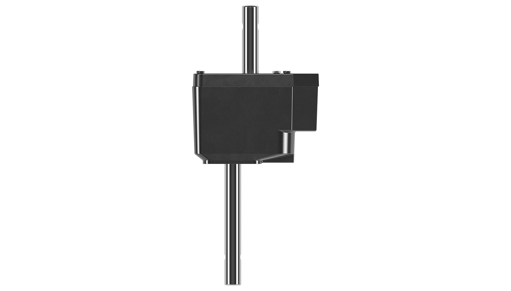
Spur gears
- Used with worm gear and bevel gear operators for reduced handwheel rim pull effort
- Can be used independent of worm and bevel gears with small nonrising stem gate valves and other nonself-locking applications that require torque multiplication; provide a low-ratio torque multiplier when used with small electric motor operators
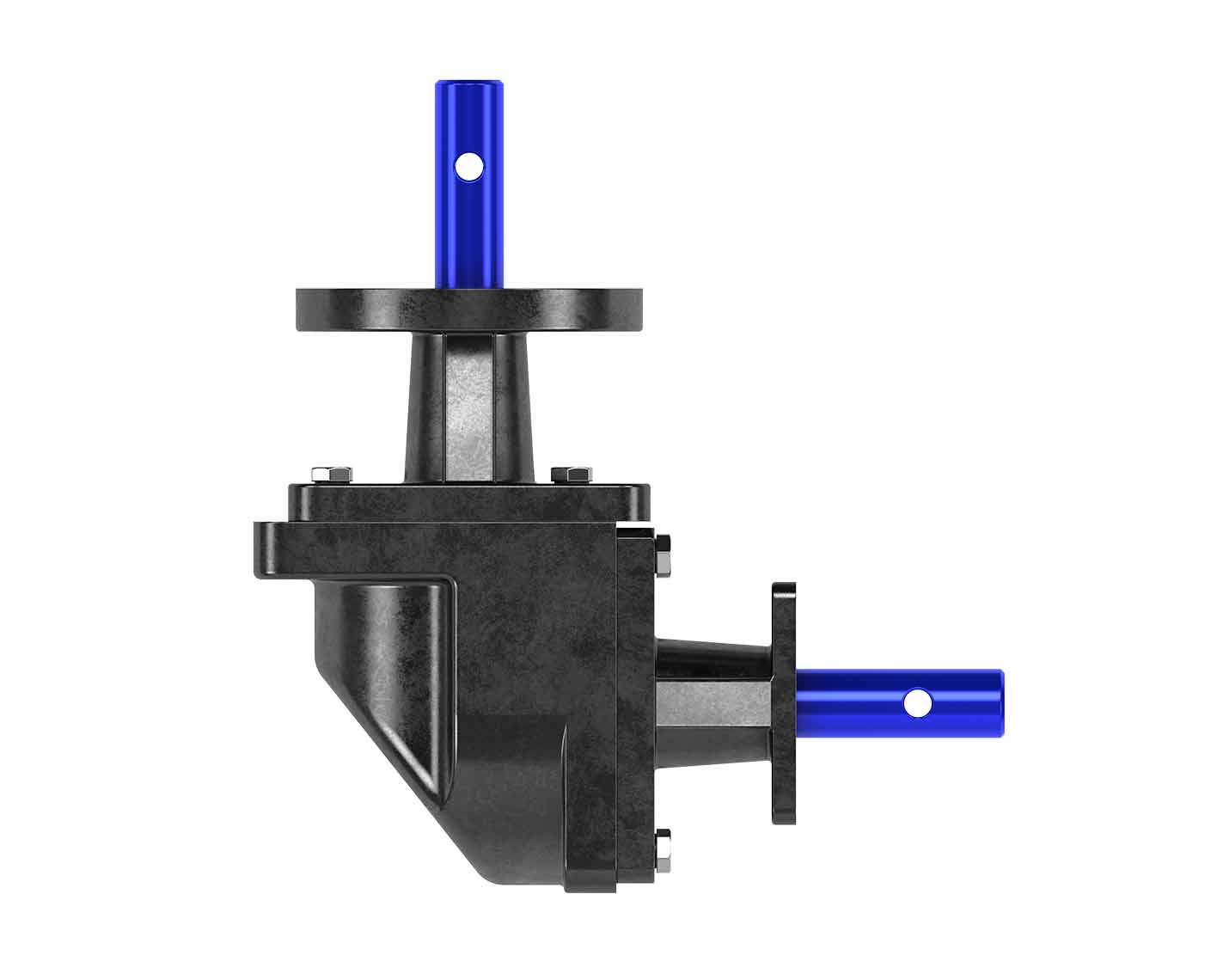
Miter gears
- For use as a close-coupled gearbox that changes handwheel input shaft direction on worm and bevel gears
- Can be used to change shaft direction by 90° on any rotating device with compatible torque values and interface dimensions
Benefits
Spur gears
- Cost-efficient design
- Efficient torque transmission with minimal power loss in gearboxes and actuators
- Simplified inspection, maintenance, alignment, and replacement
- Proven reliablility with consistent velocity ratio
Miter gears
- Efficient directional power transfer
- Greater durability and smooth operation because of improved load distribution
- Simpler design and fewer components, resulting in ease of use and maintenance compared with more complex gear systems
Features
Spur gears
- Straight teeth aligned parallel to the shaft axis
- Designed exclusively for parallel shaft arrangements
- Simple geometry that streamlines manufacturing
- Ability to maintain a constant speed ratio without angular change
- High efficiency, typically about 95%–98%
Miter gears
- Designed for intersecting (usually at 90°) shafts
- Typically use equal tooth counts for a 1:1 ratio
- Available in straight and spiral bevel configurations
- Compact design suited for angular power transmission
Tech Specs
Spur gears
| Model | Unit Weight, lbm | Max. Torque Rating, lbf.in | Gear Ratio | Turns for 90° | Standard Output Shaft Diameter, in | Standard Mounting Pattern, (Quantity) and Hole Size, in | Standard Mounting Pattern (Bolt Circle Diameter), in | Mechanical Advantage |
|---|---|---|---|---|---|---|---|---|
| 4:1 | 34 | 10,000 | 4:1 | 4 | 1.000 | (4) 0.406 | 1.250 × 2.250 | 3.2 |
| 4:1A* | 36 | 10,000 | 4:1 | 4 | 1.000 | (4) 0.406 | 1.250 × 2.250 | 3.2 |
| 6:1 | 37 | 12,000 | 6:1 | 6 | 1.000 | (4) 0.406 | 1.250 × 2.250 | 4.8 |
| 6:1A* | 39 | 12,000 | 6:1 | 6 | 1.000 | (4) 0.406 | 1.250 × 2.250 | 4.8 |
Miter gears
| Model | Unit Weight, lbm | Max. Torque Rating, lbf.in | Gear Ratio | Turns for 90° | Standard Output Shaft Diameter, in | Standard Mounting Pattern, (Quantity) and Hole Size, in | Standard Mounting Pattern (Bolt Circle Diameter), in | Mechanical Advantage |
|---|---|---|---|---|---|---|---|---|
| MT1 | 25 | 3,000 | 1:1 | 1 | 1.000 | (4) 0.406 | 1.250 × 2.250 | 0.9 |
| MT1A* | 26 | 3,000 | 1:1 | 1 | 1.000 | (4) 0.406 | 1.250 × 2.250 | 0.9 |
Notes
- All specifications are subject to change without notice.
- Bolt patterns are offset to match standard spur and miter attachment patterns on faced operators.
- * Model numbers that end in A are stand-alone models that are not made to close couple to existing products. These models also have input (handwheel) shaft and output shaft connections. Models that do not end in "A" are designed to close couple to Dynatorque 90 quarter-turn worm gears. These models have input (handwheel) shaft connections and use the input shaft of the primary operator for their output shaft connections. Models that do not end in "A" are offered as component parts that are assembled to primary operators.