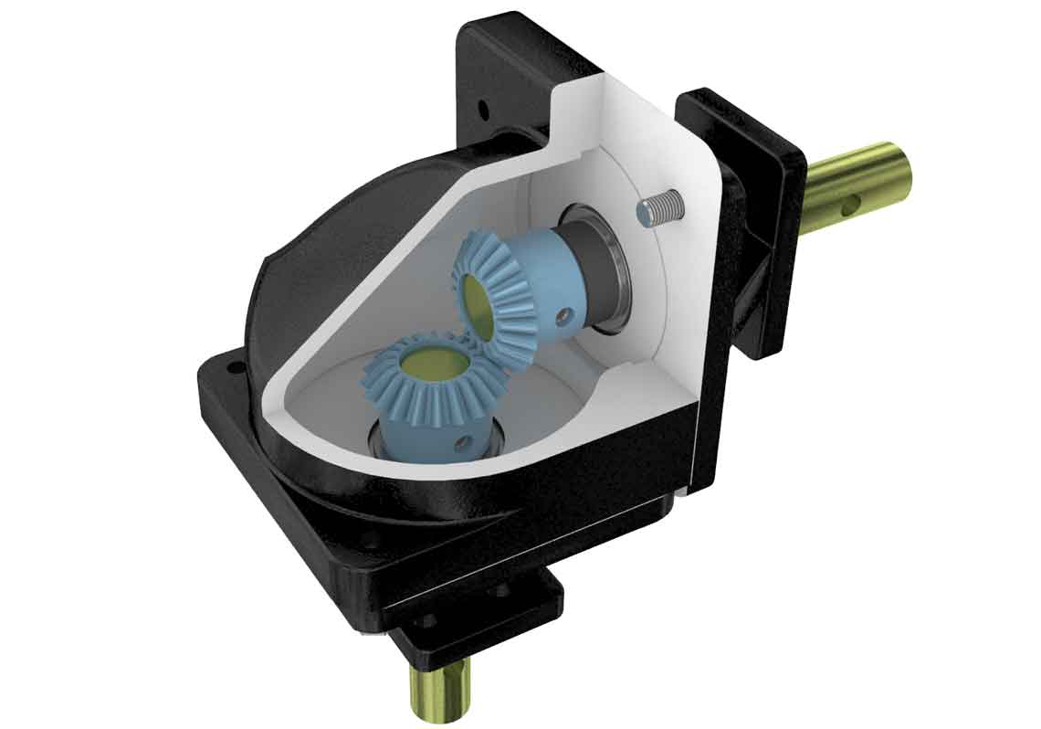
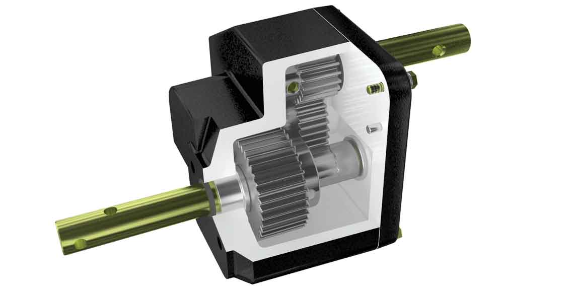
How It Works: Gears | SLB

How It Works: Gears

Published: 01/02/2015

Valves highlighted in color

Every valve requires a means of operation via cycling or actuation. Cameron offers a variety of options for operation, including handwheels, levers, gears, and actuators. Manual operators, such as gears, are relatively inexpensive and require little peripheral planning beyond the installation and orientation in the process line. Gears are simple machines that utilize a series of mechanical parts to increase efficiency, or the mechanical advantage that the user gains.

Torque is a function of force and distance. The required force (rim pull) required to open or close the valve can be decreased by increasing the length of the lever or diameter of the handwheel mounted on the valve. The industry defines specifications for the highest values personnel should exert on levers or handwheels to operate a valve. Current API specifications limit pull to 80 lbf [360 N]. The maximum lever length or handwheel diameter also is limited by industry specifications.

Tooth design and contact can also influence the gear’s efficiency. Strategically designing the shape of the gear tooth reduces the amount of contact between teeth and the bending stress on the teeth, thereby increasing durability.

Worm-Gear Operators
MAXTORQUE high-performance valve products
Worm gears.
Worm gears.

Worm gears

Standard worm gears can be configured to fit almost any partial-turn or multiturn valve, such as ball valves or butterfly valves. Worm gear operators create a mechanical advantage in torque, which reduces the amount of work or number of turns required to cycle a valve.

High-performance, high-efficiency worm gears

The double-enveloping design of MAXTORQUE high-performance valve products creates multiple start points between the gear wheels, increasing the torque capacity compared with a single-enveloping design. These gears can be easily integrated into an electric actuator package to reduce the required size of the actuator. They also increase efficiency through increased mechanical advantage.

High-performance worm gears offer a simple solution for large, high-pressure valves that are infrequently operated but where timely, safe operation is important, such as pipeline isolation or at pig launchers and receivers. High-performance gear units also carry a distinct advantage in subsea applications fast valve cycling speed is imperative to maximizing diver or ROV productivity.

Worm gears from the MAXTORQUE high-performance valve product portfolio.

Compared with standard worm gears, high-performance gears are much more efficient and better protect against backdriving. This greater efficiency results in a significant reduction in the gear ratio, which reduces the required number of turns while remaining below acceptable rim-pull requirements. Optimizing for number of turns and rim pull can provide a manual operator with a solution for applications in which traditional worm gears would exceed rim pull or number of turn limits.

Double-enveloping worm gear
Multistart worm gear design.
Bevel gears.
Bevel gears.

Bevel gears

Bevel gears are used to increase thrust efficiency to operate rising stem valves such as gate valves and rising stem ball valves. They utilize the same basic principles of a worm gear but affect thrust instead of torque. The two gear wheels in a bevel gear come together most commonly at a 90° angle and enable the transfer of movement to a new angle. Their mechanical advantage is obtained through the optimized gear ratio and increased efficiency.

Miter gears

A typical miter gear is a 1:1 bevel gear. These gears are generally used to change only the input shaft direction; in contrast, a bevel gear is used to change both ratio and shaft direction. Because of its 1:1 ratio, miter gears do not reduce required torque input into the gear operator.
Miter gears.
Miter gears.
Spur gears.
Spur gears.

Spur gears

Spur gears are added to existing gearboxes to increase mechanical advantage. However, this increases the overall gear ratio, which increases the number of required handwheel turns.
DYNATORQUE DT
Quarter-turn severe-service gear operator

Dual-input gears

Dual-input gears consist of two gears in one housing, with two input shafts and gearing. During the first 10% to 20% of travel, one gear works to overcome the break torque. Once through the break phase, the operator engages the second gear for the run torque. Because the run torque is less than the break torque, utilizing different gears for this operation can reduce the workload and closing time.

Manual override gears

Manual override gears are used in conjunction with an actuator to provide a means of manual operation if the power supply to the actuator fails. There generally are three designs to these gear types.

  • The first design utilizes a worm that is engaged only when override is required.
  • The second design, called a loss-motion override, has a coupling that is always engaged with the actuator, but the valve is free to rotate 90°. In this design, when override is needed, the gearbox rotates until it engages with the key then rotates back to operate the valve.
  • The third design utilizes planetary gears, which allow input from an actuator or manual means to rotate the valve without engaging or disengaging. Compared with a loss-motion override, the planetary gear design halves the number of turns required to operate the valve.

Gear selection

Gears are especially well suited for applications in which a portable driver is not readily available, utilities are not present for an actuator, or design simplicity is a priority. There are three forces to consider when sizing a gear for a valve— break torque, run torque, and seating torque. Break torque usually defines the size of the gear and is the highest torque value, followed by seating torque. Run torque, the torque required while the valve is cycling, usually is the lowest torque value and is the torque used for the majority of the valve’s operation.

Knowing your application and safety standards is key to gear selection. The first step in identifying the best gear type for your application is to know what type of valve will be operated. As stated earlier, worm gears are designed to provide torque for partial-turn or multiturn valves, such as ball valves, butterfly valves, globe valves, and plug valves. Bevel gears provide thrust for rising valves such as gate valves and rising stem ball valves.

The environment in which a valve will be placed affects the materials used to construct the valve. Keeping snow, rain, ice, sand, and other materials out of the gearbox helps ensure that the gears do not stick or become damaged during operation. Special lubricants and materials can be used to construct the gear wheels and housing construction considerations made to help prevent this.

Automation

The frequency of operation will also impact the gear selected. Worker safety factors, such as maximum handwheel size and turns to close, are increasingly being imposed. Valves are increasingly becoming automated as high-torque applications begin to exceed the manual actuator’s ability to meet acceptance criteria. Cameron continually explores ways to make manual actuation design better. For example, two-speed auxiliary spur options offer a higher-ratio use through the valve run torque and a lower ratio selection to meet the maximum torque requirement of the application

Products Used