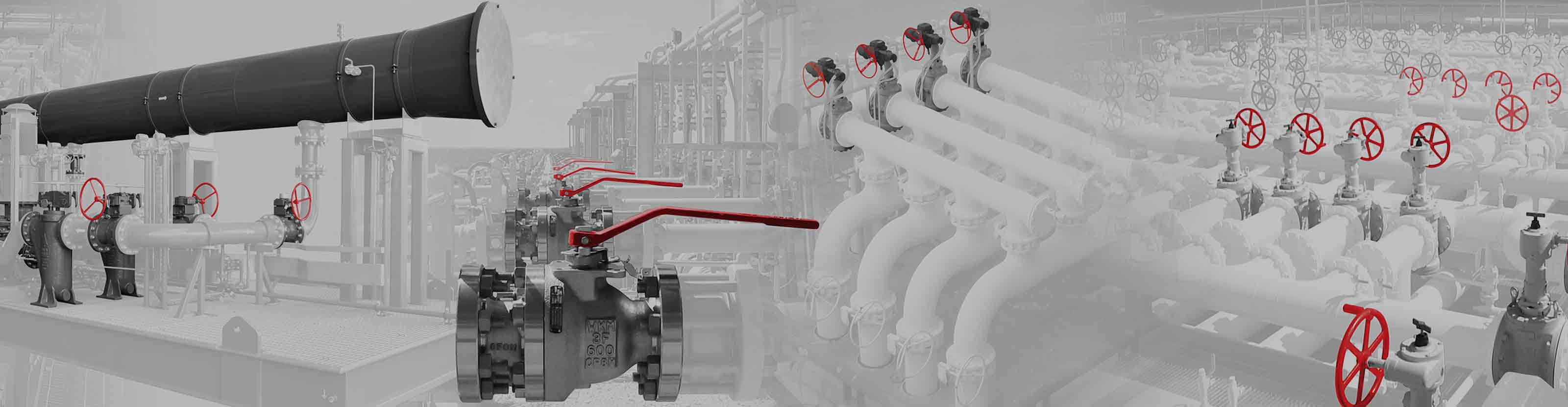
Pressure loss (pressure drop) is a decrease in pressure as measured between two points in a flowing fluid system. Pressure drop that occurs along the direction of flow in a pipe is caused by fluid friction, both in the fluid itself and with the piping surfaces, piping restrictions, or sudden changes in flow path geometry. Pressure loss is directly related to fluid velocity; specific gravity; viscosity; and the size, shape, and internal roughness of the pipe.
This means that the valve is not solely responsible for pressure drop; flow rate determines the pressure loss. To certain limits, the higher the flow rate, the greater the pressure drop, and vice versa. CAMERON T30 Series fully welded ball valves open and close at a constant rate, thereby generating low pressure loss.
Pressure relief valves
Pressure relief valves (PRVs) discharge and reduce pressure if a pressurized system exhibits a pressure increase beyond preset design limits. When the pressure in the system exceeds the valve’s set pressure point, the PRV automatically opens to relieve some of the fluid pressure. As the fluid discharges, the pressure inside the system stabilizes, and the valve will close.
Pressure regulators
Pressure-regulator valves maintain a certain pressure by automatically modulating the flow of fluid. Used in high-pressure applications, regulators help ensure that fluid supply lines or tanks are safe for various applications.
There are three elements to a pressure regulator:
- restricting element: any valve that can throttle flow, such as NEWCO gate, globe, and check valves
- loading element: the needed force for the restricting element, such as a weight, spring, or piston actuator.
- measuring elements: determines when the pressure of the flow coming into the line requires modulation of the restricting element (cycling of the valve) to properly control the desired pressure.
Pressure measurement
Pressure loss is expressed in two ways:
- flow coefficient (CV), expressing flow rate in gallons of 70-degF water per minute with a 1-psi pressure drop across a fully open valve
- equivalent length of pipe, converting the pressure drop to the equivalent pressure drop incurred in a length of pipe operating under the same volumetric and pressure conditions.
The traditional way of determining potential valve pressure loss is to set up a flow loop test, which involves continually moving 70-degF water through the valve. A gauge is used to measure the pressure loss downstream of the valve(s). This technique established the flow calculations that are still used today to determine the pressure loss across various valves.
Computers enable calculating the pressure loss across a valve without a flow loop. Engineers can use finite element analysis (FEA) to set up a simulation by entering the relevant data on the valve interior and then simulating flow. FEA gives the same results as a flow loop without having to supply the pipe, fitting, and pumps for the various valve sizes.