The Defining Series: Subsea Infrastructure | SLB

The Defining Series: Subsea Infrastructure

Published: 05/20/2016

Texture Rotating Blue
 
Defining subsea infrastructure.

To replace dwindling reserves from onshore fields or from offshore wells drilled in shallow waters, many E&P companies are turning to their deepwater prospects. Exploration or production in deep and ultradeep waters is carried out at water depths of 300 to 3,050 m [1,000 to 10,000 ft] or greater. These depths dictate that most wells be completed subsea, with wellheads, pressure-control equipment and production equipment placed at the seafloor.

From deepwater and ultradeepwater completions, produced fluids are sent to a processing facility by way of a subsea production system. A subsea production system consists of the subsea infrastructure used to produce oil and gas from offshore reservoirs. It encompasses one or more subsea wells and the subsystems necessary to deliver hydrocarbons to a fixed, floating, subsea or onshore processing facility. These subsystems can be divided into subsea trees, production controls, manifolds, jumpers, flow-lines, risers, umbilicals and processing components. Injection of water or gas back into subsea wells is also a function of the subsea production system. Generally, oil, gas and water produced from the reservoir will flow from a wellbore to a subsea tree and through a jumper to a manifold and subsea flowline. Today, many operators route the flowline to a booster pump to energize the flow as it travels between the seafloor and a riser that carries it to the surface for processing.

Seabed Equipment

The subsea wellhead, installed at the beginning of the drilling phase, provides the structural foundation for the well. The wellhead is also where the subsea tree is mounted. In some configurations, the tree contains the production tubing hanger and accommodates hydraulic and electrical lines used for managing downhole safety valves, completion valves and pressure or temperature sensors. The function of the subsea tree is to control and manage pressure and flow over the life of the well and enable any necessary intervention. The tree is the primary mechanism for shutting in the well at the seabed and serves as the interface for well reentry operations. A subsea control module (SCM) attached to the tree contains the instrumentation, electronics and hydraulics connections needed for safe operation of the subsea tree valves, chokes and downhole valves.

Sections of pipe, known as jumpers, run between subsea structures to serve as links through which fluids are transmitted. These pipe segments range in length from a few meters to hundreds of meters. A jumper is often installed to carry production downstream from the tree. The produced fluid may be routed through a multiphase flowmeter to measure production rates and volumes.

Where multiple wells produce in a subsea development, flowline jumpers from individual wells send produced fluids to a subsea production manifold (Figure 1). By routing produced fluids from multiple wells to the production manifold, the operator can reduce the number of flowlines that must be accommodated at the next step in the production chain. Upon reaching the manifold, produced fluids from the various wells are commingled before they are directed to a flowline that leads to the production platform. Injection manifolds function similarly and are used to manage the distribution of injected water, gas and chemicals to one or more subsea wells.

Figure 1. Subsea manifold. This manifold, hoisted in preparation for installation on the seafloor, will take produced fluids from several wells and route them to a flowline running to a production platform.

Subsea manifold.

Some subsea installations have a pipeline end manifold (PLEM), which connects a flowline with another subsea structure or joins a main pipeline with a branch pipeline. The PLEM can incorporate tie-in points with other components such as isolation valves, diverter valves and sensor arrays. Some PLEM designs incorporate facilities for launching pipeline pigs—devices used to clean or monitor the inside of a pipeline.

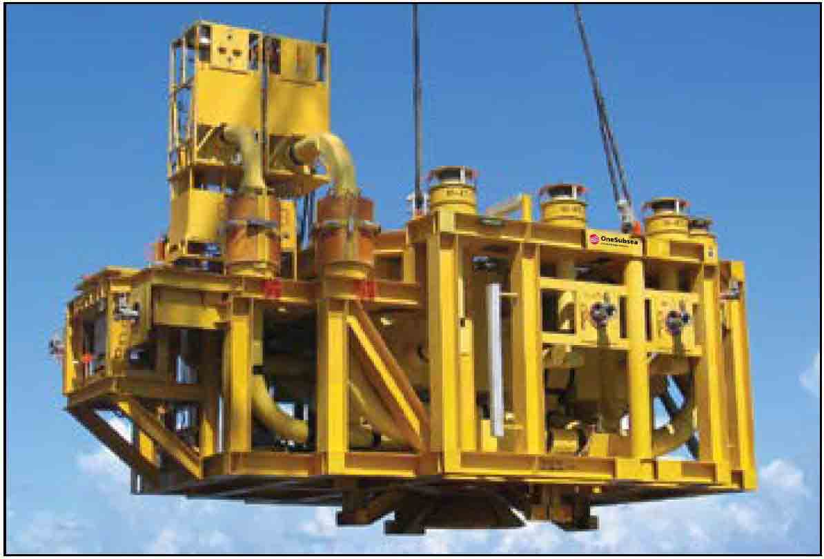
When a reservoir does not have sufficient energy to produce the fluids from one subsea component to the next, a subsea boosting pump may be installed. Boosting pumps function as a seafloor artificial lift system, increasing both flow rate and recovery by reducing backpressure on the reservoir.

Other recent advances in subsea processing are used to enhance field economics. Seafloor separation and reinjection of produced water can alleviate constrained topside water handling capacity while supplementing reservoir energy through waterdrive. Subsea gas compression, including wet gas compression, can improve viability of certain marginal developments.

Flow to the Surface

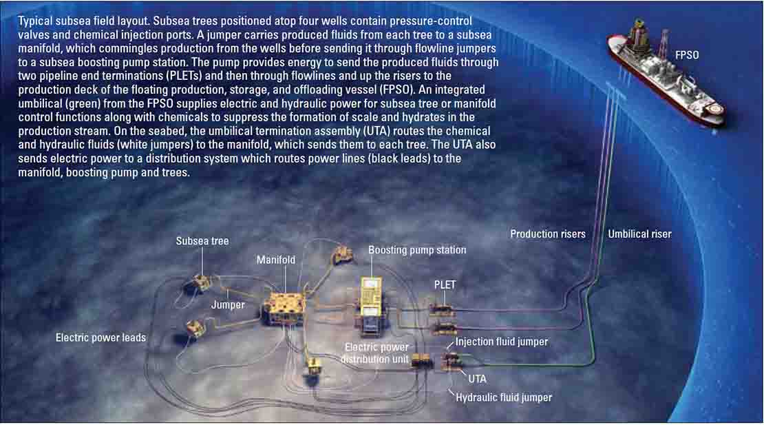
Flowlines tie one or more fields back to a production facility—a shore-based processing facility or fixed production platform in shallower waters—but in deeper waters, a semisubmersible, spar and floating production, storage, and offloading vessel (FPSO) is used. The flowlines do not necessarily trace a straight course from wellhead to platform but may bend to avoid obstacles such as existing subsea infrastructure or natural obstructions such as underwater seamounts or canyons. As it follows the topography of the seafloor, the flowline climbs gradually from the colder, deeper reaches of the field upward through relatively warmer, shallower waters before reaching the production facility.

Water depth affects temperature, which can adversely impact flow between the subsea tree and the production facility. Upon exiting the well-head, warm produced fluids may encounter deepwater temperatures approaching 2°C [36°F] at the seafloor. Heat transfer between the produced fluid in the pipeline and the surrounding seawater can cool the fluid to the point that gas hydrates start to form. The change in fluid temperature beyond the tree influences the operator's thermal management strategy. At some fields, chemicals such as methanol [CH3OH] or monoethylene glycol [C2H6O2] are injected into the system to keep the wellstream flowing then recovered on the surface and reused. Some operators use electrically heated flowlines; others use foam-insulated pipe. Some operators bury the flowline beneath the seafloor for insulation, but flowlines at certain fields require no additional heat or insulation at all. The chemistry and rheology of the produced fluids ultimately dictate which methodology is adopted.

Production flowlines run from the manifold to structures that are linked to risers that direct the flow to the production facility. Risers transport produced fluids from the seafloor to the surface production facility. Like flowlines, many risers are insulated against cold seawater temperatures. They offer a measure of flexibility to withstand subsurface water currents or movement of the floating facility.

Surface Lifeline

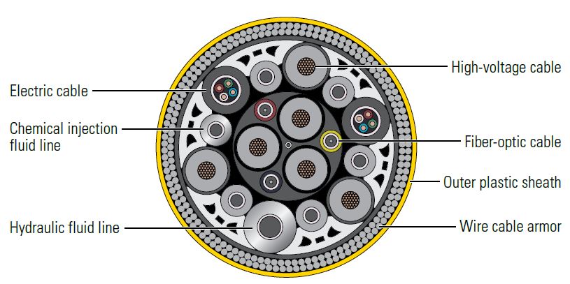
The surface processing facility provides power, control, communication and chemical injection services back to the subsea production system. These services are transmitted through a subsea distribution system using umbilicals. Multiple steel and thermoplastic conduits are often bundled together with hydraulic lines, chemical injection lines, power conductors and fiber-optic cables to form a single integrated umbilical (Figure 2). These flexible conduits require sophisticated materials and manufacturing techniques to withstand deep-ocean currents, pressures and temperatures. Power conductors provide electricity for subsea equipment and system sensors. Hydraulic lines are used to open and close subsea valves. Fiber-optic lines instantly relay sensor information and control commands between the sea-floor and the surface. Some umbilical lines pump chemicals into the production stream. Umbilicals directly or indirectly service nearly every component in the subsea production system and are critical to operating the field. The lines typically run from the surface processing facility to an umbilical termination assembly (UTA) on the seafloor, from which services are distributed throughout the field.

Figure 2. Cross section of an umbilical. Umbilicals supply electric power, hydraulic fluid, chemicals and fiber-optic communications to the subsea production system. Separate hoses, cables, injection lines and other conduits are bundled together and enclosed within an armored outer ring designed to withstand harsh subsea conditions.

Cross section of an umbilical.

Upon reaching the surface, the produced fluids are separated and treated by the processing facility. From there, an export pipeline transports the product to a storage and offloading installation or to an onshore refinery for further processing and distribution.

Oilfield Review 2016.
Copyright © 2016 Schlumberger.

Location
Offshore
Byline
Matt Varhaug, Senior Editor
Publication
Oilfield Review
Article Topics
Subsea Intervention  Subsea Installation & Commissioning Subsea Production
Products Used