How It Works: Switching Valves | SLB

How It Works: Switching Valves

Published: 01/01/2016

Valves highlighted in color

The molecular sieve dehydration unit is an important process in any plant that uses natural gas as a feedstock. Whether the plant is processing natural gas to make LNG or ammonia or is processing gas to extract NGLs, it is imperative that the gas is properly dried. Water in the gas passed along into subsequent processes can cause the formation of hydrates or destroy valuable catalyst.

Molecular sieve dehydration is currently the process by which almost all water is removed from gas. The switching valves are critical components in this process. If these valves do not perform as expected, the drying process will be compromised, and the molecular sieve drying unit will not dry the gas to the required specifications.

Mol sieve tower
Mol sieve tower
Black highly viscous oil.

Asphaltenes, Heavy Oils, and Petroleomics

Coedited by Oliver Mullins, Eric Sheu, Ahmed Hammani, and Alan Marshall

Coeditor of Asphaltenes, Heavy Oils, and Petroleomics Oliver Mullins explains how he and his partners envision using the "petroleome" of crude oil to address reservoir issues. Read the interview and follow the link to get a copy of the publication

Read More

Valve selection

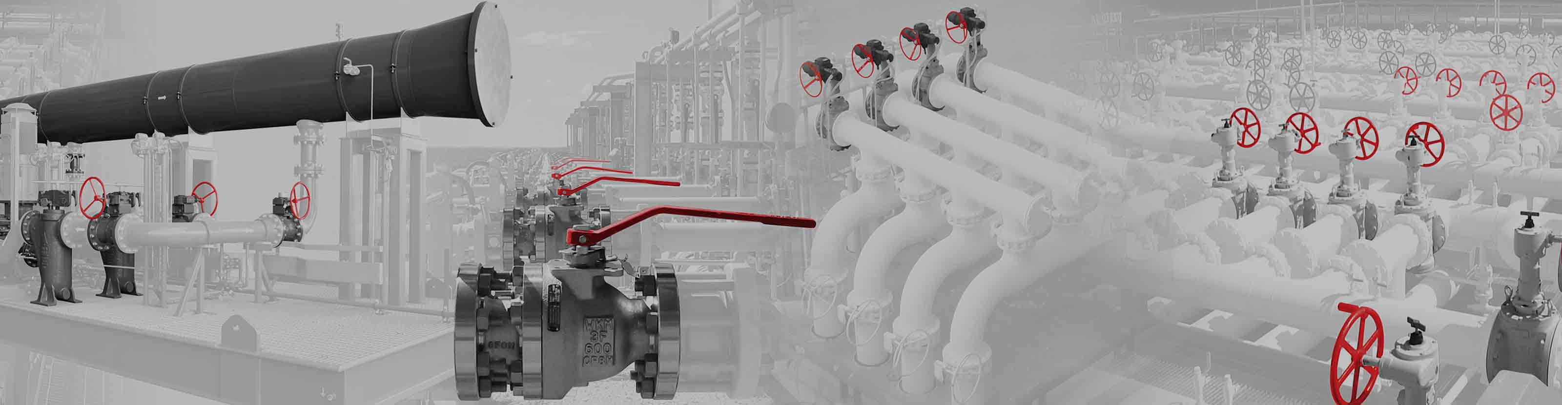
Selection of the proper valve type for use as a molecular sieve switching valve is the first step to success in an optimally operating system. Of all of the valve types used for switching valves in molecular sieve dehydration service, the rising stem ball valve has a superior and proven track record.

Characteristic requirements

In a dryer, the valve must seal tightly. If it is not possible to obtain tight shutoff, the leaky valve allows wet gas to enter the drying tower during the regeneration cycle. This leakage lengthens the regeneration cycle, wastes energy, and will not allow the desiccant to be fully regenerated, resulting in increased operating costs. The valve also must withstand high regeneration temperatures. Taking into consideration temperatures typically found in regeneration cycles and considering temporary excursions above typical regeneration temperatures, the switching valve should be designed for a maximum of 800 degF [427 degC].

The valves must be capable of withstanding the frequent cycling that is characteristic of dehydration cycles. For example, if a system is on 8-h cycles, a valve could cycle 3 times per day, 7 days per week, 365 days per year. If planned maintenance of the system is every 5 years, and this maintenance includes rebuilding of the beds and repair of the switching valves, the valve could see 5,500 cycles between repairs. Not many valve types are capable of withstanding this many cycles in a hot, dry, and sometimes hostile environment.

The rising stem ball valve provides tight shutoff, withstands frequent cycling, and handles high temperatures better than other valve types in this service. Other valve types do not have an equal track record in molecular sieve dehydration service because no other valve provides the tight seal and friction-free operation in the same manner as a rising stem ball valve.

Construction, startup, and commissioning

The construction, startup, and plant commissioning phases are critical in bringing a new plant or system online. It is possible to avoid many common problems seen in dehydration switching valves by implementing proper techniques and procedures during these phases. The most common valve issue experienced during construction and startup is foreign matter in the valves. This foreign matter typically comes from the construction of the piping into which the valves are installed.

It is recommended to clean welding residue from the lines before installing the valves, which is best accomplished by flushing the entire system. Only when the lines are clean should installation and operation of the valves commence because damage to the valves can occur if this critical cleaning operation is not performed. The most common debris found in piping and valves following construction includes weld slag and miscellaneous debris from the construction process.

Hard particles in weld slag can damage coatings, platings, and overlays. If a valve closes on the particulate, the base material can yield, compromising the integrity of the coatings. Once this occurs, the coatings—especially hard coatings such as tungsten carbide and Stellite® material—may crack and chip, exacerbating the problem. This significantly damages the valve sealing surfaces.

Damage

It is common for other types of debris to find their way into piping systems during the construction phase. These can be anything from bits and pieces of wood, juice cans, safety helmets, hand tools, or other debris left behind by construction crews. Anything left in the pipe can be a source of damage to valve components. A thorough cleaning of the entire system is critical for a successful startup.

Most molecular sieve dehydration switching valves are automated, and actuator operation directly affects valve operation and performance. For pneumatic actuators, which are the most common type used in this service, it is important that supply lines be adequately sized to deliver the appropriate volume of instrument air to smoothly open and close the valves without starving the actuator for air pressure.

Saving a few dollars by using smaller instrument lines at the time of construction can adversely affect the smooth, efficient operation of critical service valves once the plant is in operation. When the valves do not work properly, the unit does not work properly.

In cases where electric actuators are preferred, it is imperative that the actuator settings are consistent with the valve on which it is installed. Some valves are torque seated, and others are position seated. It is critical that the electric actuator be properly set; otherwise, the valve cannot close or open fully, adversely affecting performance. Improper torque settings, position settings, or both are commonplace when field personnel who are unfamiliar with the operation of the valve or actuator adjust these settings, typically resulting in poor valve performance or damage.

Examples of damage caused by weld slag during construction.
Examples of valve seat damage caused by debris.

Operation

It is normal for dust or fine powder to escape the beds, especially following new construction or the reworking of a drying tower that involved the changeout of desiccant. Valves designed for this service, especially rising-stem ball valves, will handle normal dust and carryover without issue.

Once a plant is past the construction and startup phases and has been in operation for a period of time, the most common cause of damage to valve sealing surfaces is molecular sieve desiccant escaping the screens and entering the valve sealing surfaces. This can result in damage to the closure members when the valve closes on this material, causing yielding in the base material supporting the hard facing. No valve trim is designed to adequately handle this foreign material. The solution is proper installation of the molecular sieve desiccant and ceramic balls that make up the components in the drying tower, and proper installation of the screens.

Once seat damage has occurred and seat leakage begins to cause concerns in the efficiency of the unit, a common practice for well-intentioned operators is to attempt to get the valves to seal tighter. This attempt usually means increasing the closing air pressure on the instrument regulator. This results in more closing force being applied to the valve and can result in a temporary improvement in sealing. In the long run, however, increasing air pressure above the manufacturer’s recommendations results in accelerated wear (best case) or complete failure of a key component (worst case).

Typical component damage caused by excessive closing force

Another common problem in the operation of switching valves is cycling the valves too fast, which can cause accelerated wear on critical valve components and premature valve failure. The most effective speed controls are adjustable valves placed in the exhaust ports of the three- or four-way solenoid valves on the instrument panel. If the speed controls are placed in the supply line, the actuator could starve for air, resulting in resulting in erratic operation. Placing the speed control in the exhaust port eliminates this problem and enables precise regulation of the valve operating speed. This simple but often overlooked detail can greatly extend valve operating life.

Repressuring and depressuring of the towers is dependent on many factors, such as tower size, pressure, and flow restrictors, and most experts agree that depressuring of the tower should be gradual. Some form of flow control is necessary for the tower to gradually depressure, and if this flow rate is not taken into consideration and the appropriate flow limiter installed at the time of plant design, high fluid velocities can occur when the depressuring valve opens. If this high flow rate is not assessed at the design stage, the depressuring valve is likely to be damaged. The solution is to consider the potential flow rates at the depressuring line and install the appropriate flow restricting devices. Changing trim materials in the valve does not solve this problem.

Examples of component damage caused by excessive closing force.

Turnarounds, shutdowns, repair, and maintenance

Once the plant is operational and all of the construction and startup bugs have been worked out, it is common for a dryer to operate continuously for an extended period of time, perhaps 5 years or more. Eventually, the beds will require attention, and a turnaround is scheduled. During this turnaround, it makes economic sense to inspect and repair all equipment in the system so that the next run cycle can be long and trouble free.

To ensure proper operation of the unit, rebuilding of the beds must receive the same care and attention that was given at the time of construction. It is necessary to remove and replace the ceramic balls and desiccant and to inspect and replace the screens along with all of the packing. It is common for an operator to experience problems on the next startup that are similar to those experienced during initial startup. Loading the ceramic balls and desiccant is critical, and care and attention to detail is required to keeping them in the tower and out of the valves. Many operators are forced to relearn these startup lessons immediately following a turnaround.

It is a common practice, and highly recommended, to refurbish the switching valves during a turnaround. There are two schools of thought as to the extent of repairs performed during a turnaround. One is to inspect and replace only those components exhibiting damage or wear. This approach can make sense in cases where the service support and spare parts are easily accessible. The alternate approach is to prepare to replace all components in the valve and have these parts on hand prior to shutdown.

Consideration should also be given to the actuators. Whether electric or pneumatic, the actuator is the key component in the successful operation of the dryer. Although it is easy to focus on the repair of the tower and the valves, the actuator can stop the operation of your plant just as quickly as any other critical component.

Best practices

It is recommended to choose qualified personnel to conduct the repairs on valves and actuators. Proper routine and preventive maintenance is another way to extend valve life and decrease unforeseen maintenance operations. Valve and actuator manufacturers will have a recommended preventative maintenance schedule for their products, and these schedules are based on the experience they have accumulated over the years. Following these recommendations can save much more than they cost and prove to be a valuable investment.