The Defining Series: Progressing Cavity Pumps (PCPs)
Published: 08/26/2016

The Defining Series: Progressing Cavity Pumps (PCPs)
Published: 08/26/2016
Oil production typically flows as a complex mixture of oil, gas, water and solids that regularly changes composition and rate. This dynamic environment creates complications for the artificial lift systems that are used on more than 90% of oil wells worldwide. All lift systems are susceptible, in varying degrees, to corrosive and erosive attack from solids-laden produced fluids, and this is a consideration in completion design.
Progressing cavity pumping is a cost-effective form of artificial lift that simplifies production and withstands erosive attack. Progressing cavity pumps (PCPs) displace fluid by transferring it through a sequence of small, discrete cavities formed from the turning of a helical rotor within a stator. These pumps are not only efficient in pumping viscous and abrasive fluids but are easily customized to produce liquids of varying temperatures, pressures, flow rates and solids content. Today, an estimated 50,000 wells worldwide are produced using PCPs.
PCP Architecture
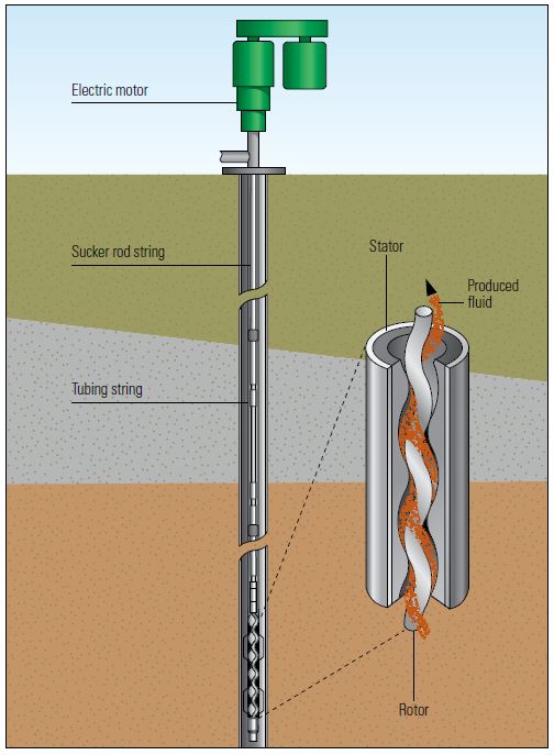
Most PCP systems consist of a downhole PCP and a drive system (Figure 1). The downhole positive displacement pump comprises a stator and a helical rotor. The stator is a steel tubular housing that has an internal bonded elastomeric sleeve with a helix design on its inner surface. It is run in the well on the bottom of the production string.
Figure 1. Progressing cavity pump (PCP) configuration. A PCP used in a well frequently consists of a helical steel rotor connected to the bottom of a sucker rod string and housed inside a stator. The stator consists of an elastomer sleeve bonded to a steel tubular housing that is part of the tubing string. An electric motor, usually on surface, rotates the rod string and the attached rotor. In some cases an insertable PCP is used, in which the rotor and stator form a single unit deployed on the rod string. The rotor and stator are aligned eccentrically to create fixed-sized pump cavities. As the rotor turns inside the stator, the motion causes the pump cavities to open and close and carry produced fluid through the pump. Highly deviated wells often use a downhole motor, eliminating the rod string.
The rotor is a small-diameter screw that has deep, round threads and a long pitch (distance between consecutive thread peaks). Typically manufactured of chrome-plated carbon steel, it is run downhole at the bottom of a sucker rod string. The helix inside the stator sleeve matches the rotor configuration, except it contains one more thread than the rotor and has a longer pitch. The rotor seals tightly against the stator and turns eccentrically inside it.
This configuration creates a set of fixed-size cavities between the rotor and stator that move as the rotor rotates and carry the production fluid through the pump in pulsation-free linear flow. The PCP is able to pump at extremely low flow rates, but seals may leak at higher pressures. This problem may be resolved by using a longer downhole pump that has more cavities; PCPs typically include 2 to 12 cavities.
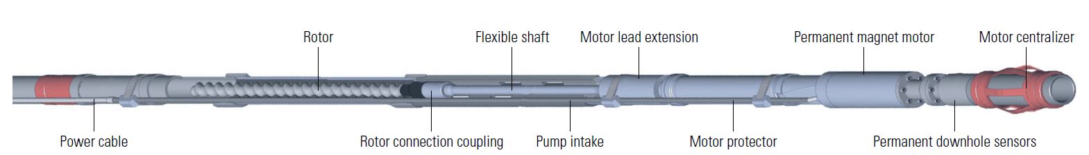
The PCP drive system is usually located at the surface and consists of a motor that rotates the rod string, which in turn rotates the rotor within the stator. However, in wells that have long lateral sections or exhibit a high degree of deviation, operators may install subsurface electric motors to turn the rotor and avoid rod and casing wear (Figure 2). In deviated and horizontal wells, these rodless PCP systems may reduce failure rates by 30% to 50% compared with PCPs that use conventional surface drive systems.
Pros and Cons
PCP systems often have specific downhole designs for a given set of field conditions: fluids, solids content and temperature. They deliver overall system energy efficiency—the ratio of motor lift power to initial input power in kilowatts, expressed as a percentage—of between 55% and 75%. PCPs are relatively easy to install and operate, and require less maintenance.
When the stator is lined with an appropriate elastomer, the pumps resist abrasion and are able to produce fluids containing high concentrations of sand and other solids. They also operate within a wide temperature range; some PCPs operate reliably at temperatures up to 120°C [250°F]. The pumps do not contain valves or reciprocating parts that may clog or lock up and they are designed to limit the rate of shear, or relative motion between adjacent layers of the flowing production fluid. This shear rate control helps limit agitation, fluid emulsification and instances of foaming that might cause processing problems downstream. At the surface, the drive system has a simple design with a small footprint and low profile, and it emits low noise levels.
However, PCPs have an upper production rate limit of approximately 800 m3/d [5,040 bbl/d] for large-diameter pumps and significantly less for small-diameter pumps. Current PCPs have a true vertical well depth limit of about 2,000 m [6,500 ft].
In addition, these pumps are sensitive to the downhole fluid environment; for example, the stator elastomer has a tendency to swell or deteriorate when exposed to certain fluids, such as those used in acid stimulation treatments. PCPs may exhibit volumetric efficiencies of less than 30% in wells producing substantial quantities of gas and greater heat retention in the pump, which may lead to elevated elastomer temperatures and reduced pump life. Paraffin control can also be problematic in waxy crude production scenarios because the rotational movement of the rod string precludes the use of scrapers for paraffin removal.
Other threats to PCP run life include rod string and tubing failures in directional and horizontal wells and increased incidents of leakage caused by excessive vibrations in high-speed applications. When PCPs operate without fluid, the pump stator deteriorates rapidly.
Applications in Artificial Lift
Operators choose PCP systems for wells characterized by high-viscosity fluids and high sand cuts. In heavy oil wells, where produced fluid viscosity ranges from a few hundred to more than 10,000 cP [10 Pa.s], PCPs may be deployed as one part of a production system. These systems may include streamlined rod strings that have minimal flow restrictions, injection of diluents such as light petroleum products or water to reduce fluid viscosity and heated or buried surface flowlines. The optimal selection of elastomer type and pump size may be a trial-and-error process of varying pump parameters and tracking system performance.
PCP systems are also used to lift production fluids in wells that have highly variable downhole temperature profiles and those containing elevated levels of carbon dioxide [CO2], methane [CH4], hydrogen sulfide [H2S] or aromatics and paraffins. Any of these factors, alone or in combination, can impact pump operating life by attacking the elastomeric material in the stator. Operators must therefore carefully prescreen elastomers to select the material that exhibits the best performance for the conditions expected.
Wells with reservoir temperatures ranging from 40°C [104°F] to 100°C [212°F] are suitable for PCPs. However, reasonable run lives in these wells require elastomers capable of withstanding these temperatures without experiencing significant swelling or debonding from the metal sleeve; elastomer integrity limits the use of PCPs in extreme-temperature applications, such as steam-assisted gravity drainage (SAGD) operations.
PCP systems are a common lift method for dewatering coalbed methane wells. Produced water from these wells typically contains high concentrations of suspended sand from hydraulic fracturing, coal particles and dissolved solids. Although these pumping systems can handle the majority of particles, pumping efficiency drops in the presence of coal particles that are 20 mm [0.8 in.] or more in diameter; such particles can become lodged in the pump and cause increased operating torque, stator tearing or pump seizing. Slotted pump intake or tailpipe assemblies can be installed to capture large coal particles before they enter the PCP while allowing fines and water to pass. To prevent gas ingress into the pump, which might lead to heat generation and pump burnout, the pump intake is typically located below the perforations or near the bottom of openhole well completions.
Surface Applications
Surface applications of PCPs include transfer of multiphase fluids from wells to collection stations and transport of crude oil from onsite storage tanks to offsite storage facilities. Because PCPs exhibit a high tolerance for rocks, cuttings, sand and other solids commonly found in drilling mud returns, they may be used to move drilling mud from storage tanks into centrifuges and to feed drill cuttings from the shale shaker into the cuttings dryer.
Operators use PCPs to pump produced water to hydrocyclones or flotation units and to transfer skimmed oil from these units to storage tanks. They may also be used to return fluid to upstream separators to extract more oil before final disposal. During hydraulic fracturing operations, PCPs are employed to dose chemicals and proppants into the fracturing fluid that is pumped downhole.
Recent Developments
Because PCP stators routinely wear out faster than rotors, the industry is focused on stator design innovation. In addition to more robust elastomeric materials, PCP providers have developed all-metal stators. Such a stator would enable the PCP to withstand the rigorous operating conditions of enhanced oil recovery methods that expose the pump to temperatures as high as 350°C [600°F], to steam and to produced fluids that have diverse fluid viscosities, pressures and flow rates.
To address premature pump failures caused by insufficient fluid levels, recent innovations address pump automation and optimization. Known as pumpoff, a lack of fluid in the pump causes increased internal temperatures and elastomer burnout, which forces operators to replace pumps sooner than would otherwise be necessary.
Solutions to pumpoff-related failures range in complexity and scalability and depend on the needs of the well. Simple variable frequency drives (VFDs) may be deployed to control motor speed and torque by varying input frequency and voltage, which helps regulate the temperature, pressure and flow rate of fluids moving through the pump. More sophisticated optimization systems are available that integrate a VFD with a control system that remotely monitors pump performance and production through surface and downhole sensors. Such control systems can automatically route commands to the VFD to fine-tune pump performance, thus optimizing flow rates and reducing pump failures and well interventions. Developments such as these promise to extend the applicability of progressing cavity pumping and help operators maximize well production.